Continue to Site

Welcome to our site!

Electro Tech is an online community (with over 170,000 members) who enjoy talking about and building electronic circuits, projects and gadgets. To participate you need to register. Registration is free. Click here to register now.

  • Welcome to our site! Electro Tech is an online community (with over 170,000 members) who enjoy talking about and building electronic circuits, projects and gadgets. To participate you need to register. Registration is free. Click here to register now.

PICKIT 2 - the latest schematic needed PLEASE!

Status
Not open for further replies.
Hi!
Sorry to go the shorter way, but I could not find anything useful with the "search"!
So if anybody have newer schematic of original PICKIT2 (if not the newest!), please, let me know! I only have an ancient schematic from "PK2 User Guide" from Microchip, and there is no any update!
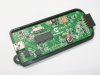
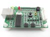
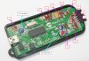
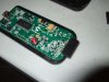
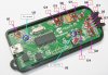
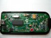
If nothing, if somebody have (or is willing to do :D) close picture of newer/newest original PK2 (these with "red button" instead of older ones with "black button") of PCB I would be very grateful!
Also, I have noticed, on blurry pic of newer orig. PK2, there is 12 transistors, while in my old schematic there are only 10 - if anyone knows what is purpose of that two "extra" transistors - please tell me!

Thank you in advance!
 
Hi,

If you are looking to build an exact copy of the Pk2 then buy one ready made as it will actually works out cheaper v parts, pcb, postage , labour time etc.

If you want to build a cut down version though still having all of the most usefull features then look at the free design in Blueroom Electronics either on his site or from pages in this forum - thats a little cheaper.

https://www.electro-tech-online.com/threads/pic-programmer-via-pic18f4455.120170/ entry #2

You do need a programmer to program the Pk2s 2550 chip so either way its still probably a better option to buy a ready made one - been there - done that
 
I have already ordered Sure-Electronic's PK2 and I just want to compare their version with latest genuine revision of MC-PK2. I only have some old schematic from 2008. and also very obsolete Sure's schematic. I know that Microchip made many revisions of PK2 (after rev 4, I think, "black button" turned to "red"). As I mentioned, I noticed (on the blurry pic) 2 extra transistors onboard and I would like to know what are these for? If there is a good reason I would try to "rework" Sure's PK2 to be as closest to the latest genuine PK2 as it can - well, I got it cheaply with PCB, main parts, housing... Even on Microchip's site you can find hints how to add extra memory (for Program-to-go) but I can't find newer schematic anywhere (like it is top-secret:confused:)!
 
Hi,

The Pickit2 User guide V2.61 2008 shows a very clear circuit diagrams of the Red button version.
I'm not aware of any changes to the circuit after that, certainly none that make any operational difference.

I believe you can tell its the Red button version by the additional 4k7 resisitors on the PGD and PDC outputs.
The Red button started production in late 2006.

The Sure unit seems to have a very clear schematic on their site dated Dec 2007 and they have even outlined those resistors in yellow, probably to highlight this very point.

Just quicky comparing both diagrams there seems little difference between the two circuits from an operational view.
The fact that the Sure unit has a Black button is I think misleading you, it uses the latest Pk2 V2.61 program so feel sure it works as a RED button does.

Just wait till you get it and check out all this features, think you will find they are all there.

A dab of paint will easily upgrade it to the RED button !
 
3v0 said:
Are you in a country where you can not order a real picKit2 from microchipDirect.com?
I'm in quite a decent European country on the verge of entering the EU but "The minimum freight cost to my country is $44.62"!!! Like they are shipping items with Concorde:mad:!

Wp100 said:
I believe you can tell its the Red button version by the additional 4k7 resisitors on the PGD and PDC outputs.
The Red button started production in late 2006.
The Sure unit seems to have a very clear schematic on their site dated Dec 2007 and they have even outlined those resistors in yellow, probably to highlight this very point.

Yes, you're right, I see that resistors now. But there are some other changes too: please see PDF in attachment! On the other two attachments: if you carefully look, you can count more than 10 transistors, it seems to me that I see even some additional IC? Second JPG shows some PK2 clone - you can easily count 12 transistors (+op.amp.IC).
 

Attachments

  • PICkit 2 Updates.pdf
    196.1 KB · Views: 343
  • pickit2_inside.jpg
    pickit2_inside.jpg
    346.4 KB · Views: 1,627
  • ViewPicture_002.jpg
    ViewPicture_002.jpg
    43.3 KB · Views: 271
Hi,

Think you are beating yourself up over nothing - as said earlier I think you will find the Sure unit will do the same as the current Microchip unit.

That update file is very old and clearly the Sure unit has those important output resistors.

I got my MC PK2 in 2007 and just opened it up - thats a Rev 5 board like your pic.

Re the transistor count - Microchip use a dual transistor package for Q1 and Q2, and the clones sometimes slightly change other bits of circuity around the op amp but achieve the same results.
 
Wp100 said:
I think you will find the Sure unit will do the same as the current Microchip unit.
Well, I really hope so:)!
Wp100 said:
I got my MC PK2 in 2007 and just opened it up - thats a Rev 5 board like your pic.
Thank you very much for your effort!
Wp100 said:
Microchip use a dual transistor package for Q1 and Q2
Yes, that must be U5 chip (6-pin) next to the button. I take them into account as 2 transistors. But, if I counted (and seen) well there is 10 transistors more = 12 transistors in total. So, IMO there is two additional transistors - in Microchip's schematic there are 8 trans. + 2 FETs (6-pin chip). It is really not so important to me, I'm just (very) curious. I see that other clone with obviously 12 transistors onboard - I contacted the seller of that clone for schematic and I'm awaiting reply. I just wonder if Microchip maybe changed something since 2007...
 
Last edited:
I think I know what's the stunt! These two "extra" transistors are not transistors, but TVS (Transient Voltage Suppression) chips! Sure's PK2 uses two 4-pin dual TVSs, Microchip, if I think right, uses them also but in 3-pin package (so I wrong identified them as transistors! What is true is that Microchip didn't update PK2 schematic since 2008; I think, as Logic Analyser Tool was added to PK later - there was a need to add some protection to I/O pins of PK - so there they are (but not on the MC schematic)!
@WP100: if you are still here, and your PK is still open :D you can check (if you want of course): two pins of each TVS must be connected to D+ and D- terminals of USB connector; ICSPCLK and ICSPDAT on ICSP terminal, and third pin from both are connected to GND.
 
Hi,

As far as I can see there is no TVS chip or similar components on the Microchip unit.

Have just checked both diagrams and they each contain 10 transistors ( allowing for 2 in U5).
Checked my actual MC PK2 and again just the 10 transistors , its the updated board with the 4k7 output resistors on the component side of the board, like that first jpeg of yours and not like that rework jpeg.

Have not heard of any MC hardware update for the Logic Analyser tool ? - I have used the LA and mine works fine.


If you want the definative answer then goto the Microchip forum who should provide all the details https://www.microchip.com/forums/tt.aspx?forumid=15


Get yourself some gold plated 0.1" 6 way connectors for your PK2, they give much better long term contact than the more common tinned versions.

If you use a breadboard or similar keep the lead from the PK2 to the board as short as possible 150mm max, above that you can get strange random problems.
 
Wp100 said:
Get yourself some gold plated 0.1" 6 way connectors for your PK2, they give much better long term contact than the more common tinned versions.
If you use a breadboard or similar keep the lead from the PK2 to the board as short as possible 150mm max, above that you can get strange random problems.
Thanks for advices, and, again, for your efforts and patience with me!

Anyway, if you are willing, please check again pics in attachment! Can you PLEASE tell me what are markings on PCB for that red circled components (3-pin transistor-like) - I mean Q1, U1 or so? On the smaller, very blurred picture you can see the same components from the other angle.

TIA, and sorry to annoy you!
 

Attachments

  • PK2.jpg
    PK2.jpg
    531 KB · Views: 233
  • PK2_2.jpg
    PK2_2.jpg
    29.3 KB · Views: 224
Hi,

Was taking some other photos so thought I would see how a close up of the pk2 would come out.
Think you can see all the parts and the silk screen ok

The blue wire is my mod, the Pk2 can only supply about 25ma to the target circuit, I have sacrificed pin 6 ( only used by LA ch3) and connected it to the +5v on the USB socket so I have 500ma USB power available to my dev board.
 

Attachments

  • pickit2hires.jpg
    pickit2hires.jpg
    418.9 KB · Views: 264
Wp100 said:
Was taking some other photos so thought I would see how a close up of the pk2 would come out.
Think you can see all the parts and the silk screen ok
Yes, I can see all clearly! There is no many pictures of PK2 (especially not of genuine PK) with so many details - actually, it is the only I found by now! And what to say than THANK YOU again! When I receive my PK2 I will do the same, so the others see what is inside + (maybe) a little review!
Wp100 said:
The blue wire is my mod, the Pk2 can only supply about 25ma to the target circuit, I have sacrificed pin 6 ( only used by LA ch3) and connected it to the +5v on the USB socket so I have 500ma USB power available to my dev board.
As I can see, you also replaced ICSP connector with gold-plated?

Greetings!
 
Hi,

No, everything on there is original Microchip apart from the blue wire.

I meant its better to use a gold plated 6 way 0.1" connector to plug into the Pk2s socket, rather than the tin plated ones.
 
I'll try to found gold plated headers - I have just ordered (because I won auction) 20pcs 40-pin male header strip (800 pins!) for 0,99$ :D (ordinary, not gold-plated). And also I have to find that red button ;)! Just kidding, of course (well, maybe from cosmetic reasons)!
 
Status
Not open for further replies.

Latest threads

New Articles From Microcontroller Tips

Back
Top