Continue to Site

Welcome to our site!

Electro Tech is an online community (with over 170,000 members) who enjoy talking about and building electronic circuits, projects and gadgets. To participate you need to register. Registration is free. Click here to register now.

  • Welcome to our site! Electro Tech is an online community (with over 170,000 members) who enjoy talking about and building electronic circuits, projects and gadgets. To participate you need to register. Registration is free. Click here to register now.

PIC24F with LCD please help!!

Status
Not open for further replies.

Dinnin

New Member
So I am working on my first project and was trying to get my schematic down before i started learning to code. I bought the "learning to fly PIC24" book. I have a few beginners questions;

1. My project will include a 4x4 keypad and a 16x2 LCD screen with the PIC24FJ64GA002 controller, can i hook all of this up to a 28 pin PIC24?

2. I plan to use the basic 16x2 LCD hd44780, but i have no idea how to lay it out on my schematic, which pins go to which D0-D7, do i want 8 bit or 4 bit? I can find examples every where for a PIC16F/PIC18F but no PIC24. Just what to plug in where?

3. Also is there a standard way of hooking up the hardware to make coding the LCD/KEYPAD easier?

Thanks in advance for any help and if my question are amateur sorry again its my first project!
 
Last edited:
So I am working on my first project and was trying to get my schematic down before i started learning to code. I bought the "learning to fly PIC24" book. I have a few beginners questions

I think your approach is a little backwards. It would probably be more benificial for you to learn the programming side of things first and then lay out your schematic. Plus you may decide to change which I/O pins you're using throughout the course of programming and debugging. Just my opinion.

I'm not familiar with the book you purchased. What language does it teach? Does it come with an IDE?


1. My project will include a 4x4 keypad and a 16x2 LCD screen with the PIC24FJ64GA002 controller, can i hook all of this up to a 28 pin PIC24?

Yes.

The 4x4 keypad will require 8 pins and the LCD can be run from as few as 6 pins in write only 4-bit mode.


2. I plan to use the basic 16x2 LCD hd44780, but i have no idea how to lay it out on my schematic, which pins go to which D0-D7, do i want 8 bit or 4 bit? I can find examples every where for a PIC16F/PIC18F but no PIC24. Just what to plug in where

The program that you write to the PIC to run the LCD will dictate which pins go to where. The examples for the 16 and 18 families will be helpful for you to learn the theory of operation. The 24 family is 16 bit while the 16 and 18 families are only 8 bit but the basic theory of micro controller operation and driving an LCD will not be much different.

I found this tutorial for driving an LCD from a PIC 16F84. If you can learn the concepts in the tutorial, you should be able to adapt it to your PIC.

3. Also is there a standard way of hooking up the hardware to make coding the LCD/KEYPAD easier?

For the keypad, one popular way of doing it is to connect each of the 4 columns to a different I/O pin and then each of the 4 rows to seperate I/O pins. You then program the PIC to scan through the columns one by one and look to see which rows are high.

Check out this application note:

AN529

Most of the I/O pins on any given PIC (with some exceptions) can all do the same things as the other pins. What they do will depend on what you program them to do. That's why it doesn't really matter which pins you connect your components to as long as the program is writen accordingly.
 
Thanks so much for the response I had thought programing was the important part. Maybe i should have chose a PIC18F/PIC16F way more helpful info on those.
 
Thanks so much for the response I had thought programing was the important part. Maybe i should have chose a PIC18F/PIC16F way more helpful info on those.

Info and tutorials for 16 and 18 family PICs are more widely available as you said. I personally think one of those would be better for a beginner. The 16F877A is a very popular model that's got lots of tutorials written for it floating around the web. You can buy one for between $5 - $10. Even if you decide to downgrade PICs, I would think the book you bought would still be helpful. The basic concepts of micro controllers will not be different between the 24 and 16 families. Good luck!
 
Last edited:
The book i got is actually been very helpful it teaches the pic24 in C. But I think I will stick with the PIC24F and just power through it figure if i go through this entire book i should be ready to go. I just noticed in the later chapter it actually has LCD code and tutorials
 
Hi,

Have to agree with Vne147 that using a 16F or 18F chip would be a much easier way for a beginner to start as they are so much more supported in both Assembler and C

The chip you specify, don't know if you have yet bought it ? its only one of a couple that are made in DIP form, all other pic24s are SMD so that may be a consideration for the future builds.
 
Last edited:
Hi,

Have to agree with Vne147 that using a 16F or 18F chip would be a much easier way for a beginner to start as they are so much more supported in both Assembler and C

The chip you specify, don't know if you have yet bought it ? its only one of a couple that are made in DIP form, all other pic24s are SMD so that may be a consideration for the future builds.

I have not bought that exact chip it was just recomended to me however i did buty the PIC24FJ256GB110 development board it has an lcd hooked to it and i thought it would help me learn. If this is really going to be a big problem i will switch ASAP and just return the devo board.

All i know was i was recomended the pic24FJ64GA002 and a SPI based LCD thats all. But if you think it will take me much longer to learn and very little help available then I will switch i wish i had got this info from you guys first, its what i get for jumping the gun i got about 2 month to finish this is time is kind of a factor.

Also i dont even know what you mean when you say DIP and SMD. Also my book talks about interfacing my LCD with pins called PMD and my pic has none of these pins, do you know if those are only for the 44 pin or higher chips or if there are 28 pins set up that way? if that makes any sense.
 
Last edited:
If you're going to code in C, then it doesn't matter if you use a 16-bit or 8-bit pic. The pic24 is overkill for your simple application, but it does have a lot more C friendly features than the 8-bit pics do (I'm not talking about libraries, just the chip features itself.) You can get all of the 16-bit pics in DIP packages, unless you need more than 20+ IO lines.

The concepts are exactly the same between the 8-bit and 16-bit chips. It's just the way they are implemented that is changed somewhat.
 
Hi,

Well from your first post it sounded like you were wanting to make up your own dev board, but now you have one - not sure if it is a Microchip Explorer16 board ? - didn't think they used that chip.

As you have that it would seem worth while to continue rather than move to another chip type - think you should try going though the examples of that book on your dev board which will teach you a lot - then the hardware issues should be a lot clearer for you.

Good luck.

Well i got the devo board to practice running the code however i have to build my own custom board with the LCD/Keypad, i thought i would use the devo board to learn and test. I have spent some time going through the LCD interface on in the book however it interfaces with the pic on the pic on the explorer 18 board, its not the same as the one i got or the one i had been told to use on my project.

I might need to start a new topic for these questions but i will ask them here any way.

1. The pic24fj64ga002 with 28 pins is what i was told to use on my personal board for this project, however the book i got teaches how to use the LCD with a HD44780 controller which i will get also, however it wires the PIC to pins PMWR.PMRD,PMA0,PMD1,PMD#0-7. On the PIC24FJ64GA002 are these the same as the RB#? just I/O pins.

2. If theyare I/O pins i should just be able to use whatever I/O pins i want on the 28 pin PIC, in the book they use somthing called PMP, can I also use this on the PIC24FJ64GA002 b/c this way seems very simple?

3. Also when looking through the example it says the PMDATA will be published on the PMP data bus (PMD0-PMD7). Does the controller automatically know which pins are where? I don't see any where in the C example code that assigns anything to the I/O ports?

As stated above i am just diving right into this so if my questions make no sense i am sorry.
 
The PMD refers to Peripheral Module Disable
**broken link removed**

They are standard TRI STATE ports which you can use to control anything, as mentioned before by vne147 your LCD will require just 6 pins, if in write mode.
Your 4x4 will require 8 pins, that means that you are using just 14 pins, so you have a few left for other control features if needed.

The 24 series upwards just have more peripherals / features on them, they program quite similar to the 16F/18F series.

A 16F or 18F program would require minimal changes to make them work on a 24F.

Wilksey.
 
The 24FJ is a 3.3v part. Your LCD is probably a 5v device. The 24FJ does have 5v-tolerant pins, but you will need external pullup resistors. You will need to be careful which pins you use since not all have 5v tolerance. You will need both 5v and 3.3v regulators. You need a low-ESR cap on VddCore. You will need to power the board on an ICD2 since the ICD2 cannot supply 3.3v power.

If it's C code, in general it'll work on the 24F just like the 18F. There will be some differences, the config bits will all have to change, you need to config the oscillator, you need to set the ADPCFG bits, you need to configure the 5v tolerant pins as open-drain.
The 24F is supported just fine with Microchip's MCC compiler.

The 24F is a lot of chip for this project. Due to it not being 5v, and its cost, I wouldn't choose it from the beginning. If you already have it, well, it's a fine chip. If you want to do more stuff later, it's a pretty powerful little toy.
 
Last edited:
1. The pic24fj64ga002 with 28 pins is what i was told to use on my personal board for this project, however the book i got teaches how to use the LCD with a HD44780 controller

The HD44780 is a common LCD driver IC. When the PIC "talks" to the LCD it will be sending data to the HD44780. The HD44780 IC will in turn take the data from the PIC and change the LCD display accordingly. The data must be sent according to a specific protocol in order for the HD44780 to understand it. The program you write on the PIC should make sure that the data is properly formatted.

There are several ways you can write a program to send the properly formatted data. Your can have your program manually format the data or you can use a pre-written library that formats the data for you.

In the first case, it doesn't matter which pins on the PIC you connect to which pins on the LCD as long as your program is written for the specific way you decided to connect everything.

For the second case, the pins you use to connect the PIC with the LCD depend on the specifics of the library you are using. Some libraries require you to use only certain output pins while other libraries allow you to specify which pins you will use in the function prototype. I don't know anything about the library your book uses (if it is in fact using a library) so in that case I would just follow the example.

We might be able to help you more if you supply a schematic and your code.

it wires the PIC to pins PMWR.PMRD,PMA0,PMD1,PMD#0-7. On the PIC24FJ64GA002 are these the same as the RB#? just I/O pins.

They are the same in the respect that they are both I/O pins that can be used to control whatever you want based on your programming and what you externally hook up to them.

2. If theyare I/O pins i should just be able to use whatever I/O pins i want on the 28 pin PIC, in the book they use somthing called PMP, can I also use this on the PIC24FJ64GA002 b/c this way seems very simple?

Not sure what PMP is but you should be able to use any I/O pins you want as long as your program is written accordingly.

3. Also when looking through the example it says the PMDATA will be published on the PMP data bus (PMD0-PMD7). Does the controller automatically know which pins are where? I don't see any where in the C example code that assigns anything to the I/O ports?

The controller does not automatically know which pins are which. Once the PIC is connected to the LCD (i.e. HD44780) the data that gets output by the PICs I/O pins is controlled by the program that is written to the PIC. So, just hooking up the PIC's output pins to the LCD like it's shown in the book on it's own is not enough to ensure proper operation. I would assume that if this book is worth the paper it's written on, that the way the book tells you to connect the PIC with the LCD would work with the code example provided but I don't know that for sure.
 
1. The pic24fj64ga002 with 28 pins is what i was told to use on my personal board for this project, however the book i got teaches how to use the LCD with a HD44780 controller which i will get also, however it wires the PIC to pins PMWR.PMRD,PMA0,PMD1,PMD#0-7. On the PIC24FJ64GA002 are these the same as the RB#? just I/O pins.

2. If theyare I/O pins i should just be able to use whatever I/O pins i want on the 28 pin PIC, in the book they use somthing called PMP, can I also use this on the PIC24FJ64GA002 b/c this way seems very simple?

3. Also when looking through the example it says the PMDATA will be published on the PMP data bus (PMD0-PMD7). Does the controller automatically know which pins are where? I don't see any where in the C example code that assigns anything to the I/O ports?

As stated above i am just diving right into this so if my questions make no sense i am sorry.
This part features a Peripheral Pin Select Crossbar, which is a godsend to board designers because most peripherals- both input and output- can be assigned to the pins which work out best on the board. I can do some REALLY complicated stuff with a single-sided board with PPS and the wires won't need jumpers. Pins labeled "RPn" are remappable.

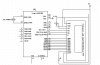
However, the Parallel Master Port- PMP- is NOT a remappable peripheral. It's permanently tied to the pins labeled "PMxxx". If your demo board does not wire the LCD to these pins, you cannot use the PMP. However, if they ARE wired to the PMP pins, the PMP can still be turned off and the LCD controlled through the pins used as regular port pins.

You don't need the PMP to talk to an LCD. In fact IMHO it'll unnecessarily complicate the project. And it won't teach you much, frankly, the PMP is a very specific module so it's not gonna teach you much about how IO works. Unless you SPECIFICALLY want to learn to use the PMP, just write to the port pins like 99.9% of people using PICs and LCDs. Code written for the PMP would need some significant rewrite to use the port pins- then again, there's like a million pieces of C code out there for controlling LCDs with PIC through the normal port pins.

The use of the PMP requires a part with a PMP, like the 24FJ64ga002. A limited subset of the PIC product lines have a PMP, and the way the PMP module works may vary. Ports, however, ANY PIC with enough pins can do that, and the way the ports work does not vary, C tasks written for the 16F will generally work on an 18F, 30F, 24F, and 33F.

What's the difference? Well, I can write all of 16 Port B's output pins to 1 (high) at once as "LATB=0xffff;" PIC 18F uses 8 bit ports at most.
The PMP allows you to configure the PMP module and write to a FIFO buffer to send the words out. But for an LCD, the writes are so simple it's way more complicated (and risky, the modules sometimes have "gotcha" problems where it won't work the way you wanted, or even errata bugs) than just writing the port directly.

I recommend you configure the LCD for 8-bit writes. You will need to be sure that you wire all the LCD data bus pins to a single port, in order. D0=RB0, D1=RB1, ... Or D0=RC0, D1=RC1, ...
 
Last edited:
I would assume that if this book is worth the paper it's written on,

The book, Programming 16-Bit PIC Microcontrollers in C, Learning to Fly the PIC24,
is written by a senior Microchip engineer , Lucio Di Jasio
 
The book, Programming 16-Bit PIC Microcontrollers in C, Learning to Fly the PIC24,
is written by a senior Microchip engineer , Lucio Di Jasio

It sounds like it is worth the paper it's written on...and probably some other paper too. :D
 
I am able to find lots of example code on how to do the 18f in 4bit mode with the hd44780 controller. However i am having problem findinding example code for the 8bit mode. But you think the 8 bit mode would be easiest for codeing, and manipulating on the pic24f?
 
BTW this is a basic schematic i put together for the LCD portion of my project. I may just give up and use an 18F since their are full blown code examples that work and the stupid book only taut how to write the code in the PMP format which i wrote and compiled successfully but have not ordered a chip or lcd yet so cannot test it this code is soooo different from all teh example code on line its hard to compare. Also below is the code i wrote with the help from the book that is suppose to work i guess, if the pic24 has the PM pins which i dont think the PIC24FJ64GA002 has.


#include <p24FJ256GB106.h>

#define LCDDATA 1
#define LCDCMD 0
#define PMDATA PMDIN1

#define LCDbusy() LCDread( LCDCMD) & 0x80
#define LCDadder() LCDread( LCDCMD) & 0x7F
#define getLCD() LCDread( LCDDATA)

#define putLCD( d) LCDwrite( LCDDATA, (d))
#define LCDcmd( c) LCDwrite( LCDCMD, (c))
#define LCDhome() LCDwrite( LCDCMD, 2)
#define LCDclr() LCDwrite( LCDCMD, 1)

void initLCD( void)
{
// PMP initialization
PMCON = 0x83BF; // Enable the PMP, long waits
PMMODE = 0x3FF; // Master Mode 1
PMAEN = 0x0001;

// init TMR1
T1CON = 0x8030; // Fosc/2, prescaled 1:256, 16us/tick

// wait for >30ms
TMR1 = 0; while( TMR1<2000);// 2000 x 16us = 32ms


//initiate the HD44780 display 8-bit init sequence
PMADDR = LCDCMD; // command register
PMDATA = 0b00111000; // 8-bit interface, 2 lines, 5x7
TMR1 = 0; while( TMR1<3); // 3 x 16us = 48us

PMDATA = 0b00001100; // display ON, cursor off, blink off
TMR1 = 0; while( TMR1<3); // 3 x 16us = 48us

PMDATA = 0b00000001; // clear display
TMR1 = 0; while( TMR1<100); // 100 x 16us = 1.6ms

PMDATA = 0b00000110; // increment cursor, no shift
TMR1 = 0; while( TMR1<100); // 100 x 16us = 1.6ms
} // initLCD


char LCDread( int addr)
{
int dummy;
while( PMMODEbits.BUSY); // wait for PMP to be available
PMADDR = addr; // select the command address
dummy = PMDATA; // initiate a read cycle, dummy read
while( PMMODEbits.BUSY); // wait for PMP to be available
return( PMDATA); // read the status register

} // readLCD


void LCDwrite( int addr, char c)
{
while( LCDbusy());
while( PMMODEbits.BUSY); // wait for PMP to be available
PMADDR = addr;
PMDATA = c;
} // writeLCD


void putsLCD( char *s)
{
while( *s) putLCD( *s++);
} //putsLCD

main( void)
{
initLCD();
putsLCD( " please work");
while ( 1)
{
}
}
 

Attachments

  • LCD Set up.jpg
    LCD Set up.jpg
    89.5 KB · Views: 1,027
Last edited:
whoops, delete
 
Last edited:
Status
Not open for further replies.

Latest threads

New Articles From Microcontroller Tips

Back
Top