Continue to Site

Welcome to our site!

Electro Tech is an online community (with over 170,000 members) who enjoy talking about and building electronic circuits, projects and gadgets. To participate you need to register. Registration is free. Click here to register now.

  • Welcome to our site! Electro Tech is an online community (with over 170,000 members) who enjoy talking about and building electronic circuits, projects and gadgets. To participate you need to register. Registration is free. Click here to register now.

PIC24F to sence a Bulb State

Status
Not open for further replies.

drkidd22

Member
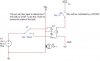
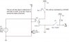
I have a circuit that will control alight bulb from a wall switch or a PIC24F. What I need to do next is to tell the pic if the bulb is ON/OFF. The only way I could think of doing it is to make another circuit from TP1 and maybe use an OptoCoupler, but I'm looking to see what you guys think. Also let me know if there are any imperfections on my circuit or anything else that I might want to do.

Thanks,
Jose
 

Attachments

  • bulbCircuit.JPG
    bulbCircuit.JPG
    21.6 KB · Views: 243
The only way I could think of doing it is to make another circuit from TP1 and maybe use an OptoCoupler,
Assuming J1 is an independent wall switch that the PIC has no control or knowledge of, then yes, an opto circuit connected to TP1 is the way to go.
A funky method would be a photo sensor positioned really close to the bulb, but that probably isn't practical. It would allow you to detect a burned out bulb though.
 
Last edited:
24F does seem like overkill, but who knows what else it is doing. Another method, which is even simpler, is to wire the switch to the 24F and let the 24F be in control of the light at all times:
 

Attachments

  • bulbCircuit.JPG
    bulbCircuit.JPG
    22.4 KB · Views: 254
Last edited:
Well, I'm using a color touch screen LCD hooked up PIC24F and using with microchip's graphics library. So with a circuit like this I can display on screen when the light bulb is on/off and I can turn it on/off as well from touch screen. I have 8 Bulbs working right now from it. Still gotta do some more work on it. I don't want the 24F to be in control at all times because I will be using this project at my home in Dominican Republic and we loose power from the grid all the time even though the PIC will be powered separectly, also another reason for the PIC24 is so that I can remotely control it from internet. This is going to be a long project, but I'm almost half way done.
 
Last edited:
I need help finding which Optocoupler to use. I think Vishay has a very long list of them. I'm not too familiar with them.
 
Use one designed for AC input. ie: One that has two back to back LEDs in it like this one does:
https://www.vishay.com/doc?83722
You can also use an ordinary DC opto, but you'll need an external diode in parallel to protect the LED from reverse bias.
 
Status
Not open for further replies.

Latest threads

New Articles From Microcontroller Tips

Back
Top