Continue to Site

Welcome to our site!

Electro Tech is an online community (with over 170,000 members) who enjoy talking about and building electronic circuits, projects and gadgets. To participate you need to register. Registration is free. Click here to register now.

  • Welcome to our site! Electro Tech is an online community (with over 170,000 members) who enjoy talking about and building electronic circuits, projects and gadgets. To participate you need to register. Registration is free. Click here to register now.

PIC18F452 and ULN2003A and Relay Pin Connection Diagram

Status
Not open for further replies.

softlab

New Member
Dear Sir,

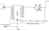
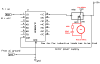
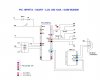
Anyone can help me to connect the PIC to Relay thro' ULN2003A (to run alarm when Interrupted Occurred). I have used PIC18F452 in my project. Now Everything works fine. I have connected 6V Buzzer to PIC thro' ULN2003A. It works. But, I like to connect alarm which runs at 230V. I have 12V Relay on my hand. It has 5 pins. I know only little about Relay and it pins. I know how relay works. But I don't know how to connect the relay from ULN2003A. If anyone provide help with pin diagram, it will be very helpful. Thanks in advance.

IDE : MPLABv8.63
Compiler: MPLAB C18 v3.37.01
 
Here a little something to go by
 

Attachments

  • ul2003relay.PNG
    ul2003relay.PNG
    4.2 KB · Views: 8,664
Thanks a lot Mr. be80be. Yesterday I got some help from microman on chat. He helped me a lot to make the circuit works. Can you pl tell me that whether we have to use diode to protect the PIC from relay spikes(Back emf) or is it enough to just connect it to ULN2003A GND as you shown in the circuit diagram?

Once again thanks for your help Mr. be80be.

hi,
On his diagram 'Burt' has already shown the COM connection to +Vs, the ULN has in built suppression diodes, all linked to COM.
 

Attachments

  • AAesp01.gif
    AAesp01.gif
    19.6 KB · Views: 1,118
Last edited:
One more thing Mr. ericgibbs. I have connected everything as shown in the circuit. If I connect COM of Relay to 110V AC to run a motor what should I do? Will the ULN take all the responsibility to take care of Back-emf?
 
One more thing Mr. ericgibbs. I have connected everything as shown in the circuit. If I connect COM of Relay to 110V AC to run a motor what should I do? Will the ULN take all the responsibility to take care of Back-emf?

hi,
The ULN diode will suppress the back emf from the relay COIL.

Add the R and C across the motor, its a snubber that helps to reduce relay contact damage and electrical 'noise'
 

Attachments

  • ul2003relay.PNG
    ul2003relay.PNG
    10.8 KB · Views: 1,801
I don't have 100K and 100nF cap on my hand now. I have to buy tomorrow and use it on the circuit and let you know. Now PIC 18F452 runs at +5V input (along with MAX232N to communicate thro' RS232 to GSM Modem). I like to run the PIC using Cell Phone Battery rated +3.6v, 1500mAh (available around +3.45V to +3.5). Just I replaced the existing current source with battery it won't works. Anything I have to add/modify in my circuit. Please help me.

The circuit is the 100% same except PIC16F877A (Here I have used 18F452).
 

Attachments

  • Circuits_16F877A.JPG
    Circuits_16F877A.JPG
    64.5 KB · Views: 661
hi
Its a 100 R not 100K.
The MAX232 operates from 4.5V thru 5.5v Max, so 3.6V is not acceptable.

EDIT:
There are no caps shown on the MAX232, is this just a drawing error.???

Look at the MAX3232 for 3.5V operation.
 

Attachments

  • max3232.pdf
    597.1 KB · Views: 404
Last edited:
for simplicity, I didn't mention the caps that are connected to MAX232N. Currently I am using GSM Modem. So I have to use MAX232N. But in near future I am going to communicate GSM Module which runs at 3.6v and can accept TTL signal from PIC. I guess it is OK to use 3.6v, 1500mAh cell Phone Battery. Am I correct?
 
for simplicity, I didn't mention the caps that are connected to MAX232N. Currently I am using GSM Modem. So I have to use MAX232N. But in near future I am going to communicate GSM Module which runs at 3.6v and can accept TTL signal from PIC. I guess it is OK to use 3.6v, 1500mAh cell Phone Battery. Am I correct?

hi,
Did you read what I said about the MAX232 operating voltage.???

and the alternative MAX3232 that will work at 3.5v.
 
yes. I read. It requires min 4.5 to 5.5v max. So, it can't be used if we are using 3.6v battery. Now you told MAX3232 will work at 3.5 volt. I have to try now. I like to avoid MAX IC to preserve battery current. Actually, I need to communicate the GSM Module from PIC18F452. So, we can use 3.6v battery to operate entire thing. No need for MAX IC. Am I right?
 
yes. I read. It requires min 4.5 to 5.5v max. So, it can't be used if we are using 3.6v battery. Now you told MAX3232 will work at 3.5 volt. I have to try now. I like to avoid MAX IC to preserve battery current. Actually, I need to communicate the GSM Module from PIC18F452. So, we can use 3.6v battery to operate entire thing. No need for MAX IC. Am I right?

OK,
Do you have a model number for your GSM module, so that I can check the 'TTL' levels you stated.
 
SIM900B (or) SIM900D GSM Module - from SIMCOMM
 

Attachments

  • SIM900_DATASHEET.pdf
    472.2 KB · Views: 925
Last edited:
Yes. So that we can send straight a way back and forth TTL signal to and from GSM Module and PIC. No need to worry about MAX for conversion. Can I use 3.6v battery to operate GSM Module and PIC?
 
Yes. So that we can send straight a way back and forth TTL signal to and from GSM Module and PIC. No need to worry about MAX for conversion. Can I use 3.6v battery to operate GSM Module and PIC?

hi,
In the GSM data it says: Supply Voltage range: 3.22 V - 4.2 V, nominal: 3.8 V
So at 3.6Vs the PIC and GSM will be OK.
 
Status
Not open for further replies.

Latest threads

Back
Top