Continue to Site

Welcome to our site!

Electro Tech is an online community (with over 170,000 members) who enjoy talking about and building electronic circuits, projects and gadgets. To participate you need to register. Registration is free. Click here to register now.

  • Welcome to our site! Electro Tech is an online community (with over 170,000 members) who enjoy talking about and building electronic circuits, projects and gadgets. To participate you need to register. Registration is free. Click here to register now.

PIC18F simulation problem !!!

Status
Not open for further replies.

loup-garou

New Member
Hi all,


I'm a begginer in PIC18F programming (I started yesterday :D ), I'm using Microchip C18 compiler in MPLAB, I compiled some simple programms that I found in the C18 getting started from Microchip web sitehttps://ww1.microchip.com/downloads/en/DeviceDoc/MPLAB_C18_Getting_Started_5129 5f.pdf

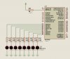
like this one for led flashing:

Code:
#include <p18cxxx.h>
#pragma config WDT = OFF

void delay (void)
{
unsigned int i;
for (i = 0; i < 10000 ; i++)
;
}


void main (void)
{
TRISB = 0;

while (1)
  {

/* Reset the LEDs */
PORTB = 0;
/* Delay so human eye can see change */
delay ();

/* Light the LEDs */
PORTB = 0x5A;
/* Delay so human eye can see change */
delay ();

  }

}

I build and simulate it with MPLAB SIM succesfully, but when i tried to simulate it in schematic using ISIS the PIC did nothing !!! :confused:

how can I solve this problem ??


I joined the entire project + ISIS simulation file above


thanks in advance for any kind of help. :)
 

Attachments

  • Second Project.zip
    30.9 KB · Views: 236
Last edited:
Is it connected to either RB0, RB2, RB5, RB6 Since thats all your going to turn on with that 0x5A hex there.... wheres the actual schem?

“PORTB = 0” sets all eight pins of the PORTB register to ‘0’ or to a low voltage.
“PORTB = 0x5A” sets four pins on PORTB to ‘1’ or to a high voltage
(0x5A = 0b01011010).
 
add 10K resistor from MCLR to Vcc and it will work (attached the fixed ISIS schematic and the snapshot).
 

Attachments

  • Second Project_fixed.zip
    38.4 KB · Views: 241
  • brisi.jpg
    brisi.jpg
    44.6 KB · Views: 686
Last edited:
arhi said:
add 10K resistor from MCLR to Vcc and it will work (attached the fixed ISIS schematic and the snapshot).

Hi arhi,

thank you very much for helping me :)

I would like to know why we should do this and why we don't put Crystal oscillator and connect Vcc and Vss in ISIS schematics ?


AtomSoft said:
Is it connected to either RB0, RB2, RB5, RB6 Since thats all your going to turn on with that 0x5A hex there.... wheres the actual schem?

Code:
“PORTB = 0” sets all eight pins of the PORTB register to ‘0’ or to a low voltage.
“PORTB = 0x5A” sets four pins on PORTB to ‘1’ or to a high voltage
(0x5A = 0b01011010).

Hi AtomSoft,

sorry, I did not understand your remark ! :confused:
 
Last edited:
loup-garou said:
I would like to know why we should do this and why we don't put Crystal oscillator and connect Vcc and Vss in ISIS schematics ?

You should pull up MCLR to high as it is active low, meaning, if it is low, the pic is in reset state.

As for the oscillator circuit, you do not have to add oscillator to the pic for ISIS to perform successful simulation as when you look at the component property of the pic in ISIS you have to enter the frequency PIC will run hence no need for external oscillator.

You do not connect Vcc/Vss as ISIS assumes that PIC is powered up by 5V source
 
Ok let me explain more... Since i dont use ISIS i cant see the schem but i was just stating that the HEX Value 0x5A in binary is 01011010 which is
RB0 = Output
RB1 = Input
RB2 = Output
RB3 = Input
RB4 = Input
RB5 = Output
RB6 = Input
RB7 = Output

Hence only 0, 2 5 and 7 on PORTB will have the LEDs on
 
AtomSoft said:
Ok let me explain more... Since i dont use ISIS i cant see the schem but i was just stating that the HEX Value 0x5A in binary is 01011010 which is
RB0 = Output
RB1 = Input
RB2 = Output
RB3 = Input
RB4 = Input
RB5 = Output
RB6 = Input
RB7 = Output

Hence only 0, 2 5 and 7 on PORTB will have the LEDs on

hi AtomSoft,

in the Code ,PORTB (RB0,...RB7) is clearly set as an output

Code:
TRISB = 0;


hence, any LED connected to PORTB can be Flashed depending on the PORTB assignment:
Code:
/* Light the LEDs */
PORTB = 0x5A;

for exemple if we want them all to flash we have to write:

Code:
/* Light the LEDs */
PORTB = 0xFF;
 
arhi said:
You should pull up MCLR to high as it is active low, meaning, if it is low, the pic is in reset state.

As for the oscillator circuit, you do not have to add oscillator to the pic for ISIS to perform successful simulation as when you look at the component property of the pic in ISIS you have to enter the frequency PIC will run hence no need for external oscillator.

You do not connect Vcc/Vss as ISIS assumes that PIC is powered up by 5V source

thank you arhi for your explanations :)

but why when we put power in MCLR we don't specify the voltage ?

otherwise , what are the min-max values ?


thanks in advance.
 
Last edited:
arhi said:
The Vcc power rail in ISIS is 5V by default, you can configure your power rails (you can make more of them, one for 3.3V, one for 5V, one for 12V etc...) using menu Design/Configure power rails

thanks a lot !! ;)
 
i knew that i was just simply stating that only those 4 will flash and not all so to make sure they had it on either 4 and not the other. I dont have that ISIS stuff so i could not see a schematic so couldnt tell if he wired correctly
 
AtomSoft said:
i knew that i was just simply stating that only those 4 will flash and not all so to make sure they had it on either 4 and not the other. I dont have that ISIS stuff so i could not see a schematic so couldnt tell if he wired correctly

ok,


bye the way, which simulator do you use for your schematics ?
 
Status
Not open for further replies.

Latest threads

Back
Top