Continue to Site

Welcome to our site!

Electro Tech is an online community (with over 170,000 members) who enjoy talking about and building electronic circuits, projects and gadgets. To participate you need to register. Registration is free. Click here to register now.

  • Welcome to our site! Electro Tech is an online community (with over 170,000 members) who enjoy talking about and building electronic circuits, projects and gadgets. To participate you need to register. Registration is free. Click here to register now.

PIC16F877A senior design project NEED HELP

Status
Not open for further replies.

engineergirl27

New Member
Hello all,
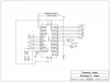
I in a senior design class and I am trying to program a PIC16F877A to be used as a weather analyzer. It needs to take input from a temp sensor lm35, a humidity sensor, a wind speed sensor, and out put temperature, heat index and wind chill. i have a program for a2d conversion, and I have some experience, but I am getting overwhelmed with how much i have to do, so i was wondering if anyone could help me out with some code. To output the wind chill or heat index i need to do some math, I don't know how to program equations. I have the temp and humidty both going into PORTA and I don't even know if I can do that. The wind speed is a digital input and that is going into portC. PLEASE HELP:confused:

Elizabeth
 
What have you tried, so far?

At least a flow diagram of the main sequence?
 
Hi Elizabeth,

Welcome to the forum! Are you expected to program in C or assember? What languages are you already familiar with? Do you have a schematic worked up yet?


Torben
 
Here is what I have

Ok , I don't know if this is what you guys are looking for but here it goes.

Input all the time from the temp from port A
Display the temp all the time
take input from the humidity sensor through port A
Heat index will be calculated for temps above 27 C/ 80 F with relative humidity > 40 %
Take input from windspeed sensor
Wind Chill will be calculated for temps below 4 C and 40 F with wind speeds > 5 mph
one of these will be displayed when one push of a push button switch
There are equations that will calculate these.

I have the a2d program in ASM and the input of a switch, but these are two seperate programs, and need to be put together with equations.

Here are the two programs I have that work on it, but now i need to put them together. I could also program in C but it has been awhile since I have worked with it. I hope you guys understand what i am trying to do.


A2D
; This code will light a LED on portC pin RC2/CCP1 and
;display the 8 bit hex value on portB LEDs or bargraph. The CCP1 LED
;will glow from bright to dim as the pot varies the pulse width.
;Connect an O-scope to CCP1 and watch the PW vary. This code can be
;used on other PICs but you will have to change the code to fit it's
;instruction set. One wire on pot goes to +Vdd and the other end
;of the pot goes to -Vss/ground. The wiper goes to RA0 input pin.
;You can use any input signal source as long as you don't exceed the
;chips max specs. for example, a slow sine or ramp wave(1-5Hz) will
;flash the CCP1 LED. Make sure you use a common ground for the
;signal generator and PIC board.


#include <p16F877a.inc>
LIST p=16F877a
errorlevel 1,-302 ;to disable MPLAB bank warnings.
__config _XT_OSC & _PWRTE_ON & _WDT_OFF &_LVP_OFF
;
;Some versions of MPLAB use _LVP_OFF
;This sets all portB pins to output.
;/*---------Declare Registers
STATUS EQU 03
ADCON EQU 08
PORTB EQU 06
F EQU 1
W EQU 0
;/*---------Set up chip parameters
CLRF CCP1CON ;CCP MODULE IS OFF
CLRF TMR2 ;CLEAR TIMER2
MOVLW 0X7F ;
MOVWF PR3
CALL A2D
CLRF INTCON ;DISABLE INTRPTS ANDCLEAR T0IF
BSF STATUS,RP0
BCF TRISC,2 ;MAKE PIN 2 PWM OUTPUT
CLRF PIE1 ;DISABLE PERIPHERAL INTS
BCF STATUS,RP0
CLRF PIR1 ;CLR PER INT FLAGS
MOVLW 0X2C ;PWM MODE, 2LSBs OF DUTY CYCLE=10
MOVWF CCP1CON
BSF T2CON,TMR2ON ;TIME2 STRTS TO INCREMENT
;
;CCP1 INT IS DISABLED
;DO POLLING ON THE TMR2 INT FLAG bit
;
PWM_PERIOD_MATCH
BTFSS PIR1,TMR2IF
GOTO PWM_PERIOD_MATCH
;
;UPDATE THIS PWM PERIOD AND THE FOLLOWING PWM DUTY CYCLE
;
BCF PIR1,TMR2IF
A2D bsf STATUS,RP0
MOVLW B'00000001'
MOVWF TRISA ;All outputs except RA0.
CLRF TRISB ;RA0 is wiper of 50k pot/Vin
CLRF TRISC ;PortB is 8 LED output to show
MOVLW B'00001110' ;Hex value of Vin from pot.
MOVWF ADCON1 ;left justified, RA0 = input
;/*-----Set up A2D parameters
MOVLW B'11010111' ;prescaler 1:256 tmr0, internal clock
MOVWF OPTION_REG
BCF STATUS,RP0
MOVLW B'01000001' ;a2d = on, ch0, fosc/8
MOVWF ADCON0
;/*-----Delay loop to settle A2D, similar to de-bounce???
mnloop btfss INTCON,T0IF ;50us loop delay @ 4Mhz
goto mnloop
;/*-----Stop timer0 interrupt
BCF INTCON,T0IF
BSF ADCON0,GO_DONE ;start a2d conversion
WAITA2D NOP ;wait 4 finish
BTFSC ADCON0,GO_DONE
GOTO WAITA2D
;/*-----Put A2D/PWM value in W and send to ports.
MOVF ADRESH,W ;upper 8 bits-ignor lower 3
MOVWF CCPR1L ;PWM is output on pin 13 of 16F873
MOVWF PORTB ;output Hex value to LEDs
RETURN ;DUTY CYCLE IS 25% OF PWM PERIOD

END

Dip switch representing the windspeed sensor

; FILE: helloDip.asm - WORKS!
; AUTH: P.Oh
; DATE: 1.0 - 04/13/02 16:30
; DESC: Read Port A DIP switch and display on Port B LEDs
; NOTE: Tested on PIC16F84-04/P.
; Page numbers in code are in Easy Pic'n book
; REFs: Easy Pic'n p. 60
#include <p16F877a.inc>
list p=16F877a
radix hex

;----------------------------------------------------------------------
; cpu equates (memory map)
myPortC equ 0x07
myPortB equ 0x06 ; (p. 10 defines port address)
;----------------------------------------------------------------------

org 0x000
start movlw 0xFF ; load W with 0xFF make port C input (p. 45)
tris myPortC ; copy W tristate to port C outputs (p. 58)

movlw 0x00 ; load W with 0x00 make port B output
tris myPortB ; copy W tristate to port B

movf myPortC, w ; read port C DIP and store in W
movwf myPortB ; write W value to port B LEDs

circle goto start ; loop forever

end

;----------------------------------------------------------------------
; at blast time, select:
; memory uprotected
; watchdog timer disabled
; standard crystal (4 MHz)
; power-up timer on
 
I had one already

I did respond with a main flow prg, i don't know if it didn't work or what, here is a schematic though, I will try to repost the prgm that i had though,
 

Attachments

  • circuit1.jpg
    circuit1.jpg
    187.9 KB · Views: 1,118
Torben said:
Hi Elizabeth,
Welcome to the forum! Are you expected to program in C or assember? What languages are you already familiar with?
Torben

Hi,
Tell us the program language. I use the MPLAB assembler.

It helps to get a positive response if you can post the program you have written.

Also welcome.:)
 
Here are my programs, I tried to just post them but it didn't let me, so here are the .asm files. here is also a flow of what i need the program to do, The programs attached work by themselves, the way that I have my circuit built, but I would like to get some ways of combining them to get what i need to acheive. Thanks for any help you can give.


I am currently programming in assembly on mplab, because i do have some help from a professor and some experience in it, but I am getting lost easily. The circuit that I have shown is just my block, this is a group of 5 people and i have the microprocessor, I don't even know if the other peoples stuff will work by the time it is all said and done.


Main flow

Take inputs from the temperature as an analog frequecny
convert to digital
display all the time

take inputs from the humidity sensor as an analog voltage
convert to digital
display as heat index when push button is pressed with an equation when temps above 27 C/ 80 F with relative humidity > 40 %

take input from the windspeed sensor as a digital frequecy (8-bit binary)
display as wind chill when push button is pressed with an equation when temps below 4 C and 40 F with wind speeds > 5 mph


Elizabeth
 

Attachments

  • atod.asm
    2.9 KB · Views: 202
  • dip.asm
    883 bytes · Views: 211
engineergirl27 said:
Main flow

Take inputs from the temperature as an analog frequecny
convert to digitaldisplay all the time
The LM35 temperature sensor has a voltage output proportional to the tempr,
+10mV/C.


take inputs from the humidity sensor as an analog voltage convert to digital
display as heat index when push button is pressed with an equation when temps above 27 C/ 80 F with relative humidity > 40 %
Do you have a humidity sensor type number.?

take input from the windspeed sensor as a digital frequecy (8-bit binary)
display as wind chill when push button is pressed with an equation when temps below 4 C and 40 F with wind speeds > 5 mph
Do you have a Wind speed sensor type number.?

Elizabeth

hi,
What range of:
Temperature, Humidity, Windspeeds and Chill factor are you required to measure and to what resolution.?

These limits will effect the program maths and the displayed data.


EDIT:
Your atod.asm has a number of errors also its not necessary to define Registers and W/F.
The include 16Fxxx takes care of the defines.
PR3 is not declared.
Check your subr calls and returns, the program generates a 'stack' error.
 
Last edited:
I can see one software and one hardware problem so far.

SW3 will short out the supply if operated. R3 should be instead of the wire that connects Vcc to Vpp.

In the software, you don't have a main loop. All code that runs continuously should have a main loop after the initialise that looks something like this:
Code:
Initialise
;set start values
;setup peripherals
Main_loop
;do stuff here
;call routines 
;etc
     goto    Main_loop

I hope this helps.
 
ericgibbs said:
hi,
What range of:
Temperature, Humidity, Windspeeds and Chill factor are you required to measure and to what resolution.?

These limits will effect the program maths and the displayed data.


Temperature - LM335 not LM35-this was going to be 5 volts but it is going to be a analog frequency
Humidity - HS1101 - up to 5 volts
WindSpeed Sensor, has a whole circuit that will give an 8 bit number from 0 to 255 mph

I don't know if there is anything else you guys need to know.
 
engineergirl27 said:
ericgibbs said:
hi,
What range of:
Temperature, Humidity, Windspeeds and Chill factor are you required to measure and to what resolution.?

These limits will effect the program maths and the displayed data.


Temperature - LM335 not LM35-this was going to be 5 volts but it is going to be a analog frequency
Humidity - HS1101 - up to 5 volts
WindSpeed Sensor, has a whole circuit that will give an 8 bit number from 0 to 255 mph

I don't know if there is anything else you guys need to know.

hi E27,
The LM335 is an analog voltage output 10mV/K, its a Kelvin version of the LM35.?

I'll look thru the HS1101 humidity sensor.
I expect the Windspeed sensor outputs a continous, asychronous 8bit binary code.

Did you see the notes regarding the program that I posted.?

One point you will have to decide, is the refresh rate for displayed data.
eg;
Most weather station data has a slow rate of change, so some form of data averaging should be considered, prior to any display update.

On the temperature data, what resolution do you want to display, will 1Cdeg resolution be OK .???

Likewise for humidity , will 1% be OK.

Sorry to ask so many questions, but what you are asking has a number of solutions.

Regards

EDIT: the HS1101 is a capacitive sensor, it requires a C to F convertor, [as shown in the datasheet], it cannot be connected to PORTA as an analog signal.
 
Last edited:
The hs1101 datasheet has a schematic for a 7555 timer, it'll output a frequency between 5khz & 8khz so you'll have to convert the frequency to get the humidity reading.

When is your project due?
 
I know, this programming for me, has brought me many questions and solutions, and i think that is why I am having so many problems, I don't know which solutions is best. Yes to the nearest Degree is fine, same with the nearest 1%, I also, have a push button that is going to be pressed to show the heat index or wind chill. And i was thinking about .5 seconds or so to be refreshed
 
May 9th, I would like to get it done before that of course to get it tested. that is right the temp is in mV and the humidty is a frequency, it is difficult to keep them straight since I am not setting them up.
 
Eric,
I know, this programming for me, has brought me many questions and solutions, and i think that is why I am having so many problems, I don't know which solutions is best. Yes to the nearest Degree is fine, same with the nearest 1%, I also, have a push button that is going to be pressed to show the heat index or wind chill. And i was thinking about .5 seconds or so to be refreshed

blue,
May 9th, I would like to get it done before that of course to get it tested. that is right the temp is in mV and the humidty is a frequency, it is difficult to keep them straight since I am not setting them up.
 
engineergirl27 said:
Eric,
I know, this programming for me, has brought me many questions and solutions, and i think that is why I am having so many problems, I don't know which solutions is best. Yes to the nearest Degree is fine, same with the nearest 1%, I also, have a push button that is going to be pressed to show the heat index or wind chill. And i was thinking about .5 seconds or so to be refreshed

Hi,
Understood.

I would recommend the follow bits of test hardware in order to simulate the inputs from the various sensors.

1. A 5K0 multiturn pot, connected from +5V to 0V with the wiper going to the PIC's AN0 input, together with a DVM capable of measuring mV, for simulating the LM335 temperature sensor.

2. A variable rate square wave pulse generator, with a setting read out, to simulate the HS1101 humidity 555 osc output.

3. A 8 bit DIL switch to simulate the Wind speed input.

You say you are using 4 off, 7seg LED's,,, these will require a few extra components because of the multiplexing of
the PIC port pins required to drive them.

I would advise, that you write the program in a modular way, that is write the sub programs for each module before you integrate them in your final program.

Thats a module for each of the three sensors, the LED display, switch inputs and the maths subroutines.

I would start with the display drivers module.
This then can be used to display the outputs of the various modules as you develop them.

You say 8/9th May 2008 is the deadline, I think an experienced programmer would find it difficult to complete, fully test and debug the hardware/software in 3 weeks for this project.

Can you say which country you are posting from.?
 
ericgibbs said:
Hi,
Understood.

I would recommend the follow bits of test hardware in order to simulate the inputs from the various sensors.

1. A 5K0 multiturn pot, connected from +5V to 0V with the wiper going to the PIC's AN0 input, together with a DVM capable of measuring mV, for simulating the LM335 temperature sensor.

2. A variable rate square wave pulse generator, with a setting read out, to simulate the HS1101 humidity 555 osc output.

3. A 8 bit DIL switch to simulate the Wind speed input.

You say you are using 4 off, 7seg LED's,,, these will require a few extra components because of the multiplexing of
the PIC port pins required to drive them.

I would advise, that you write the program in a modular way, that is write the sub programs for each module before you integrate them in your final program.

Thats a module for each of the three sensors, the LED display, switch inputs and the maths subroutines.

I would start with the display drivers module.
This then can be used to display the outputs of the various modules as you develop them.

You say 8/9th May 2008 is the deadline, I think an experienced programmer would find it difficult to complete, fully test and debug the hardware/software in 3 weeks for this project.
There are other students working on the other parts of this most of which already work. Someone else is already doing all the extra hardware for the 7 segments, Also, I have all those testing already, and the AtoD and the 8 bit binary code works, I just need to know how to integrate them, which I am going to my professor for help now.


Can you say which country you are posting from.?

I am posting from the US

Elizabeth
 
Status
Not open for further replies.

Latest threads

Back
Top