Continue to Site

Welcome to our site!

Electro Tech is an online community (with over 170,000 members) who enjoy talking about and building electronic circuits, projects and gadgets. To participate you need to register. Registration is free. Click here to register now.

  • Welcome to our site! Electro Tech is an online community (with over 170,000 members) who enjoy talking about and building electronic circuits, projects and gadgets. To participate you need to register. Registration is free. Click here to register now.

PIC16F877A PWM and servos question

Status
Not open for further replies.

psecody

Member
Sorry if this question has been asked before but I've searched the forum and the internet for hours now and can't find anything to explain this to me. I also looked over Nigel's tutorial and I understand most of it but my problem is actually taking that and controlling a servo.

I understand that the servos run at 20ms periods and the first part is high and the second part is low and 1.5ms high would roughly be neutral on the servo. I understand all of that but what I'm getting confused with is figuring up the delays and how to actually program that. I've found a few articles talking about controlling a servo with a PIC but all of them are programmed in C or basic and I am trying to do it in assembly.

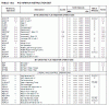
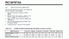
I'm using a PIC16F877A with an 8MHz oscillator. I looked here http://www.pyroelectro.com/tutorials/servo_motor/software.html and was trying to figure it out with those figures just replacing values for mine but I'm still new to micro controllers and aren't sure if I've figured these right. The part I didn't understand was the instructions per clock cycle is, how do you come up with those numbers? I looked on the data sheet and it said the 877a 20MHz 200ns instruction cycle and I think thats related but I'm not sure how.

Sorry for so many questions, I just thought I grasped the concept until I actually sat down and tried to program and failed miserably. I appreciate any help.
 
hi,
The PIC divides the crystal/clock freq by 4.

So a 4MHz xtal would give a cycle time of 1µSec

and a 20mHz / 4 = 5MHz == 200 nanoSec.

OK.?:)

EDIT: most Instructions take 1 cycle time, about 4 or so take 2 cycles.

This clip shows the cycles.
 

Attachments

  • esp02 Aug. 13.gif
    esp02 Aug. 13.gif
    52.6 KB · Views: 711
Last edited:
Thanks for the reply it helped alot. I've got all the figures now, but my problem now is I'm not a 100% sure how to use some of these numbers. Heres what I've got so far:

Pulse Duration=.9ms-2.1ms
Neutral Position=1.5ms
Pulse Refreshes at 50MHz (20ms)

Clock Frequency=8MHz=8,000,000Hz
Instruction frequency=8/4MHz=2MHz=2,000,000Hz

(This is the part I'm not sure on. I don't really get why I'm figuring how many instructions equal the ms. I know its got something to do with how to write the delay but I'm not quite sure how to write the delay. I know how to write delay but I don't know how to make them accurate to tenths of a second.)

1/2,000,000 seconds * (x)instructions=18.5ms -> 37,000,000 instructions= 18.5ms
1/2,000,000 seconds * (x)instructions=1.5ms -> 3,000,000 instructions = 1.5ms

Thanks for the help

hi,
Have a look at this link:
 
(This is the part I'm not sure on. I don't really get why I'm figuring how many instructions equal the ms. I know its got something to do with how to write the delay but I'm not quite sure how to write the delay. I know how to write delay but I don't know how to make them accurate to tenths of a second.)

1/2,000,000 seconds * (x)instructions=18.5ms -> 37,000,000 instructions= 18.5ms
1/2,000,000 seconds * (x)instructions=1.5ms -> 3,000,000 instructions = 1.5ms

Thanks for the help

It took me a while to figure the same thing out.
Just a quick example :

Let's say you have a PIC running at 1000 instructions per 1 ms, so you want to make a delay of 20ms right ?

Using the Timer1 register, which is a 16 bit separated into TMR1L (L for low) and TMR1H (H for high).

If you put the value 20000 on Timer1 doing something like this in C :

Code:
TMR1H = (20000 / 256);
TMR1L = (20000 % 256);

What will happen when I start Timer1 ?
It will decrease or increase (this is just an example) by 1 each cycle, since each 1000 instructions take 1ms (1000 instr / 1 ms) we have :

Code:
 1000 instructions -> 1ms
20000 instructions -> x

x = 20ms

Got it ?
 
@ericgibbs: Thanks for that site it helped I was really looking for something like this so that I could see how it was actually done.

@bpmelo: Thanks that helps I'm starting to figure it out.

Another thing I found that I should have included in my other questions is

Nigel's talking about the PR2 register on here where does he get the number to store in there from? Also T2CON sets the frequency of the PWM I get that part but then he goes on to say 20MHz is to high a frequency....I think I might have just figured it out that part of it out while I was typing it but I'm going to put it here and ya'll tell me if I'm doing it right. T2CON sets the period for the PWM you need to set the pre scaler to divide by so much to match 50MHz? Hmm well I thought I had it figured out but as I type it it's not making sense anymore.

hi,
The PR2 prescaler is a 8 bit divider ie: 0 thru 255 ,, 127 is the centre value, chosen to give fwd and rev operation.
The figures in the datasheet are for 20MHz, thats why Nigels says they have to be adjusted to suit the xtal frequency in use.

Look at this extract from the datasheet.
 

Attachments

  • esp06 Aug. 13.gif
    esp06 Aug. 13.gif
    20.5 KB · Views: 437
Thanks for putting up with all these questions. I still can't grasp how you set the period and the duty cycle though. I'm sorry but if someone could maybe give me an example in assembly with some comments (or a link to one though I haven't found one yet) I would really appreciate it. I think if I could see it applied I might understand it better but right now I'm more confused than when I started. Thanks again
 
ok so I've been mucking around with some code and am still lost.

This is what I came up with from a few of the data sheets on microchips website mixed with some of their examples but i don't think its at all right

Code:
	list		p=16f877A	; list directive to define processor
	#include	<p16f877A.inc>	; processor specific variable definitions
	
	__CONFIG _CP_OFF & _WDT_OFF & _BODEN_OFF & _PWRTE_ON & _RC_OSC & _WRT_OFF & _LVP_ON & _CPD_OFF


;***** VARIABLE DEFINITIONS


;**********************************************************************

	ORG 0x00
	
Setup BSF STATUS, RP0
	MOVLW 0x00
	MOVWF TRISC
	BCF STATUS, RP0
	
	CLRF CCP1CON
	CLRF TMR2
	
	BSF CCP1CON, 3
	BSF CCP1CON, 2

	MOVLW 0x14
	MOVWF PR2    ;20 to pr2 
	MOVLW 0x02
	MOVWF CCPR1L ;2 to ccpr1l 10% duty cycle

	BSF T2CON, TMR2ON ; Timer2 starts to increment


	BCF PIR1, TMR2IF ;resets the timer

	END
 
psecody;336880]ok so I've been mucking around with some code and am still lost.

This is what I came up with from a few of the data sheets on microchips website mixed with some of their examples but i don't think its at all right

Hi,
I thought that Nigel's tutorials covered the PWM.
As you are using Nigel's work, he's the best guy to answer any points on the tutorial.:)
 
Hi,
I thought that Nigel's tutorials covered the PWM.
As you are using Nigel's work, he's the best guy to answer any points on the tutorial.:)

My PWM 'tutorial' is only for driving motors - it's just one example of how to drive two motors using two channel PWM with forward and reverse. I wrote it solely because I was continually getting requests for how to drive the motors in a small robot.

There are numerous examples on here of how to drive servo's, the PWM hardware alone is useless at it - you need to use it to trigger an interrupt and continually reprogramme the PWM. I think it's Mike who has posted lots of excellent examples?, including feeding silly numbers of servos at the same time :D
 
ok so I've been mucking around with some code and am still lost.

This is what I came up with from a few of the data sheets on microchips website mixed with some of their examples but i don't think its at all right

Did you look at my recent post ? This is the thread https://www.electro-tech-online.com/threads/generating-pwm-pulse-using-16f628-timer1-comparator.41396/#post336715.

Take a look at it, maybe we can work out the solution.
Because I still can't figure out what is happening also.
 
I've posted a few servo programs. The simplest which uses software delays to control a servo is about 3 posts down in this thread. A much better version is in this thread but it is in C. You should be able to work out what it's doing and what values are required in which registers in order to use the hardware timer to generate the signal.

Edit, I found an assembler version that uses the hardware. link

Mike.
 
Last edited:
Status
Not open for further replies.

New Articles From Microcontroller Tips

Back
Top