Continue to Site

Welcome to our site!

Electro Tech is an online community (with over 170,000 members) who enjoy talking about and building electronic circuits, projects and gadgets. To participate you need to register. Registration is free. Click here to register now.

  • Welcome to our site! Electro Tech is an online community (with over 170,000 members) who enjoy talking about and building electronic circuits, projects and gadgets. To participate you need to register. Registration is free. Click here to register now.

PIC12F1571 ICSP isolation

Status
Not open for further replies.

Brian Tremaine

New Member
Hi -
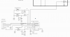
I'm having difficulty debugging with a PICKIT3 on a 12F1571. My circuit is reading three switches and controlling a PWM output. I've attached a schematic. Note, I removed C7 on switch S1 as it was loading the ICSPCLK.
I have RA1, RA2 and RA4 configured as inputs with weak pull-ups. RA0 is configured as a digital output. I used MCC to configure the pins.

One switch is directly connected to RA1/ICSPCLK and the switch is normally open. RA0/ICSPDAT also connects to the gate of a FET (high impedance). Will this work in both programming mode and in debug mode?

My other two switches are on RA2 and RA4.
My code loads and S3 (RA4) detects a switch event. However, switch S2 (RA2) is at 5V and toggles to GND and back to 5V but no switch event is detected.
After programming S1 (RA1) is sitting at 0v, as if no pullup is active.

Any hints as to my problem? I've duplicated this on two boards with the same PICKIT3.

Thanks,
Brian
 

Attachments

  • Capture1.PNG
    Capture1.PNG
    83.5 KB · Views: 233
H
One switch is directly connected to RA1/ICSPCLK and the switch is normally open. RA0/ICSPDAT also connects to the gate of a FET (high impedance). Will this work in both programming mode and in debug mode?
I wouldn't count on either of them doing what they're supposed to do with the PICKIt connected.

After programming S1 (RA1) is sitting at 0v, as if no pullup is active.
Not surprising since the PICKit could be pulling the line low. Don't expect function on pins being shared by the debugger to work when the debugger is plugged in.


Does RA2 work if you add an external pull-up? I've run into cases where the internal pull-up just didn't do it, for whatever reason. You could also try removing the capacitor. It's not needed. I'd personally remove all the pull-down caps unless the pull-up resistance was really high.

Are you debouncing your switches? It's hard to say much more without knowing how you're handling RA2 in software. Polling? Interrupts? How? You could have set up the pin wrong with copy/paste from your other buttons.

Are you telling us that if you erase everything in your MCU and just have it run an infinite loop where:
IF BUTTON IS PRESSED THEN OUTPUT HI ELSE OUTPUT LO

It doesn't work even if you hold down the button? And then release? ? You might want to do that.
 
Last edited:
Whilst the PIC is in debug mode (ie. the debug pins enabled by config fuse) those pins cannot be used for any other I/O
It's not just having the debug device connected, the pins are taken over by the debug interface on the chip, as far as I remember.

You need to disable debug to try any other functions on the debug pins. In circuit programming can still work, that's a different thing.

Edit - realised it's a PIC12.
Note that if you are working with an eight pin device, you can get a debug version (or debug header) that has a special 14 pin device with eight pins providing the standard device connections plus extra pins for ICD without taking over the normal I/O

I have a PIC12 one, it's invaluable for working with those.

Info:
**broken link removed**
 
Last edited:
Status
Not open for further replies.

Latest threads

New Articles From Microcontroller Tips

Back
Top