Hi fellows
I have built a couple of versions of sunrise lamp using analogous components. Recently I have been studying PIC programming by making various tutorials in the
internet. As my first independent PIC project I decided to make - guess what? - a sunrise lamp. I had dismantled an early version of sunrise lamp and had the
peripherals in my drawer. If allowed by the board policy I will post the schematics and the assembly listing here, maybe somebody else could be interested
in building it.
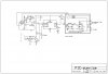
The alarm was obtained from the beeper terminal of an electronic alarm clock. The signal was rectified, filtered and amplified by a PNP transistor.
The zero-crossing signal of 50 Hz AC was generated from the secondary of a transformer after bridge rectification. A positive signal was obtained from the collector of a germanium NPN transistor (an old transistor from a dismantled portable radio). I used germanium transistor because its base-emitter voltage is low and thus one can expect a sharp zero-crossing signal from a low-voltage
source.
A cheap and simple PIC12F509 was used. The time base of the 30 min ramp was the 100 Hz line clock (zero crossing frequency). PIC’s TMR0, prescaler 1/64, was used to generate variable PWM duty cycles of 155 steps. After the 30 min ramp the program waits (the light is on) for 2 h and then shuts down the lamp and moves back to wait for a new (good) morning.
The PWM signal is leaded to an optocoupler, which fires a triac and lights the mains-connected 60W incandescent lamp. A couple of switches were added in order to reset the program and to force the lamp on or off. An indicator
light tells that the system is waiting for a new alarm.
Most of the building blocks of the schematics are not originally mine, I am too inexperienced to develop anything quite new. The zero crossing detector is
modified from **broken link removed**, the alarm clock hacking
from P.D Choudhury (ELECTRONICS FOR YOU • NOVEMBER 2006 • 99), and many assembly program features from various tutorials. However, the combination is,
at least in part, unique.
Disclaimer. I shall not take any responsibility of possible malfunction of the adjoined sunrise lamp schematics or the assembly program. Making a mains connected equipment is dangerous. If you build this sunrise lamp you must be
aware of the local regulations and of the good practise of making mains-connected equipment. In every case, you will do it on your own risk.
Mikko Järvinen
hobbyist in electronics
I have built a couple of versions of sunrise lamp using analogous components. Recently I have been studying PIC programming by making various tutorials in the
internet. As my first independent PIC project I decided to make - guess what? - a sunrise lamp. I had dismantled an early version of sunrise lamp and had the
peripherals in my drawer. If allowed by the board policy I will post the schematics and the assembly listing here, maybe somebody else could be interested
in building it.
The alarm was obtained from the beeper terminal of an electronic alarm clock. The signal was rectified, filtered and amplified by a PNP transistor.
The zero-crossing signal of 50 Hz AC was generated from the secondary of a transformer after bridge rectification. A positive signal was obtained from the collector of a germanium NPN transistor (an old transistor from a dismantled portable radio). I used germanium transistor because its base-emitter voltage is low and thus one can expect a sharp zero-crossing signal from a low-voltage
source.
A cheap and simple PIC12F509 was used. The time base of the 30 min ramp was the 100 Hz line clock (zero crossing frequency). PIC’s TMR0, prescaler 1/64, was used to generate variable PWM duty cycles of 155 steps. After the 30 min ramp the program waits (the light is on) for 2 h and then shuts down the lamp and moves back to wait for a new (good) morning.
The PWM signal is leaded to an optocoupler, which fires a triac and lights the mains-connected 60W incandescent lamp. A couple of switches were added in order to reset the program and to force the lamp on or off. An indicator
light tells that the system is waiting for a new alarm.
Most of the building blocks of the schematics are not originally mine, I am too inexperienced to develop anything quite new. The zero crossing detector is
modified from **broken link removed**, the alarm clock hacking
from P.D Choudhury (ELECTRONICS FOR YOU • NOVEMBER 2006 • 99), and many assembly program features from various tutorials. However, the combination is,
at least in part, unique.
Disclaimer. I shall not take any responsibility of possible malfunction of the adjoined sunrise lamp schematics or the assembly program. Making a mains connected equipment is dangerous. If you build this sunrise lamp you must be
aware of the local regulations and of the good practise of making mains-connected equipment. In every case, you will do it on your own risk.
Mikko Järvinen
hobbyist in electronics