Continue to Site

Welcome to our site!

Electro Tech is an online community (with over 170,000 members) who enjoy talking about and building electronic circuits, projects and gadgets. To participate you need to register. Registration is free. Click here to register now.

  • Welcome to our site! Electro Tech is an online community (with over 170,000 members) who enjoy talking about and building electronic circuits, projects and gadgets. To participate you need to register. Registration is free. Click here to register now.

PIC SMS Controller

Status
Not open for further replies.

Gayan Soyza

Active Member
I have hard coded nokias FBUS protocol & hacked many frames sent & receive by nokia by analizing the data frames using a PC terminal.

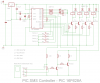
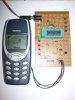
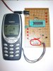
This is the hardest protocol I have experienced. I Like to show a basic project recently did. It’s a PIC SMS controller.

gsmicro: PIC SMS Controller

The latest nokia phones have a different FBUS version (3) & I’m investigating that as well, it can be accomplished by doing minor changes to the early version.

I cannot share the full code due to some reason but I can assist them to develop there stuff.
 

Attachments

  • Pic SMS.png
    Pic SMS.png
    16.3 KB · Views: 2,070
  • 5.JPG
    5.JPG
    59.4 KB · Views: 2,929
Hello i want to make this project. Please let me know how to start?Can I get a Complet project to buy from you for using it at my house?
 
hello guys i'm just wondering what you guys call this terminal that i've encircled? :D
 

Attachments

  • 5.JPG
    5.JPG
    48.5 KB · Views: 825
Ummm, a 5pin male 0.1" header ?

And where's the source code for your project? Why just post a picture showing you did it but no code to let other people do it? :)
 
Please provide us with the source code so that we can make it. If you give the code then you will not loose any thing rather you are extending your helping hand with good intention nothing else. In these days nothing should be hidden. I t should be open to all.so please share your all ideas with helping atitude.Sorry for the harsh language.:eek:
 
Hi,

I am currently building a similar project to this one. The problem I am having is with the interface from the phone (FBUS) to the PIC. Can you please explain how exactly the interface from the Nokia's FBUS to the Rx and Tx connectors on the PIC works.

Why have you used a pair of transistors on the Tx output from the phone, and why is the input to Rx going via a voltage divider because looking at **broken link removed** project which is doing the same thing, they have just plugged it in directly to the phone, through a 1k resistor.

Also presumably you are using USART in the PIC to communicate with the phone?

Thanks
 
hello
can you give me the helping hand for my project , how you connect the pic with the phone , and how to send the data from the pic to the phone ,
plz help me
 
moh.alshibli1988: You can buy a nokia FBUS cable to connect the phone. You send data using FBUS commands. Take a look on this site.
 
Hi sorry for the delay.

Actually we are dealing with 5V (PIC) & 3.3V (Phone) logic. From PIC it transmits 5V & this is too much for the phone. So I added a voltage divider to the circuit. The divider values will deliver 2.75V to the phone.

Phone transmits less than 3.3V voltage that is too low to detect on PICs receiver side so I boost up the signal using two transistors.

Note in my schematic it must swap the PICs RX & TX lines.
 
Hi

Thanks for that.

Do you reallly need two transistors in a darlington array for the boosting?
Also, do you mean that the PICs Rx goes into the phones Rx or Tx line?

Thanks again

Fred
 
Status
Not open for further replies.

Latest threads

New Articles From Microcontroller Tips

Back
Top