Continue to Site

Welcome to our site!

Electro Tech is an online community (with over 170,000 members) who enjoy talking about and building electronic circuits, projects and gadgets. To participate you need to register. Registration is free. Click here to register now.

  • Welcome to our site! Electro Tech is an online community (with over 170,000 members) who enjoy talking about and building electronic circuits, projects and gadgets. To participate you need to register. Registration is free. Click here to register now.

Pic Programming question

Status
Not open for further replies.
ok, I've added the relay driver bit to my secondary circuit. Can anyone help me with MPLab simulating an input and output so I know what's going on when the circuit is being simulated.
 
Download the trial (30 runs) of the Oshonsoft simulator, it's got buttons and lights.

With MPLAB you can open a PORTx watch window and toggle input bits with your mouse while single stepping in the simulator.
 
Last edited:
I'm having some trouble getting it to work, it compiles fine, no errors, its just that the commands aren't wanting to be issued as according to my logic idea. Look at an earlier post on this thread to find the logic as I want it to be. It's a pretty simple program, just listening to 2 inputs and activating and deactivating 4 outputs accordingly. For your information the way its set up the relay circuit is on RA0, Operation LED is on RA4, Warn LED is on RA3, and the Refill LED is on RA2. The Upper Sensor is on RB3, and the Lower Sensor is on RB2. I know it sounds weird, but that's how I have it laid out on the circuit board drawing that I made with Eagle.
Code:
#include "p16F628.inc"    ; This includes PIC16F628 definitions for the MPASM assembler
     __CONFIG _CP_OFF & _WDT_ON & _PWRTE_ON & _RC_OSC

     ORG 0x000
     GOTO Init

     ORG 0x004
     GOTO Main
Init

     BSF   03H, 5               ; go to bank 1
     movlw 0X00          
     movwf PORTA                ; porta all output
     movlw 0XFF
     movwf PORTB                ; portb all input
     clrw
     bcf  03H,5                 ; return to bank 0
     bsf PORTA,4                ; Turn on Operation LED
     btfss PORTB,3              ; If PortB,3 (Upper Sensor) = high 
     bcf PORTA,0                ; Turn off Refill Systems
     btfss PORTB,3              ; If PortB,3 (Upper Sensor) = high
     bcf PORTA,3                ; Turn off Refill LED
     btfss PORTB,3              ; If PortB,3 (Upper Sensor) = high
     bcf PORTA,2                ; Turn off Warn LED
     goto Main


Main
     btfss PORTB,2              ;if port B,2  = low
     bsf PORTA,3                ;Activate Warn LED
     btfss PORTB,3              ;if port B,2  = low
     bcf PORTA,4                ;Deactivate Operation LED
     btfss PORTB,3              ;if port B,2  = low
     bsf PORTA,2                ;Activate Refill LED
     btfss PORTB,3              ;if port B,2  = low
     bsf PORTA,0                ;Activate Refill Relay
     btfsc PORTB,2              ;if port B,2 = high
     btfsc PORTB,3              ;if port B,3 = high
     bcf PORTA,0                ;Deactivate Refill Relay
     btfsc PORTB,3              ;if port B,3 = high
     bcf PORTA,2                ;Deactivate Refill LED
     btfsc PORTB,3              ;if port B,3 = high
     bcf PORTA,3                ;Deactivate Warn LED
     btfsc PORTB,3              ;if port B,3 = high
     bsf PORTA,4                ;Activate Operation LED
     goto Main
 
I can't see how it compiles correctly as your config line is wrong. _RC_OSC is not valid and should probably be _INTRC_OSC_NOCLKOUT for the internal oscillator. You also need to turn off the comparators (put 7 into CMCON).

Mike.
 
But , how do we convert this file to hexa file. which software to use.

You use MPlab to convert the assembly file into the HEX file that is loaded into the microcontroller. It also can be used to load the program into the microcontroller when a programmer is used. Back to my issue when I build the program using PIC simulator those first 2 lines get this ;Line removed by MPASMWIN Preprocessor.
 
Last edited:
I can't see how it compiles correctly as your config line is wrong. _RC_OSC is not valid and should probably be _INTRC_OSC_NOCLKOUT for the internal oscillator. You also need to turn off the comparators (put 7 into CMCON).

Mike.

Would I put that in the Initialization area at the top of the code?
 
This is what I use for the pic16f628A

Code:
	__CONFIG	_CP_OFF & _WDT_OFF & _PWRTE_ON & _BODEN_OFF &_INTRC_OSC_NOCLKOUT & _MCLRE_ON & _LVP_OFF
	ERRORLEVEL -302

I'm not sure if this applies to the simulator but you should have a 10mS debounce circuit for when the button is pressed or things will go loopy.

Mike
 
I can understand the debouncing of the inputs, but would I have to put physical components onto the board between the IC and switches, put code into my program, or will I have to do both??
 
Ok, I've put a modest (10K) resistor in between the sensors and the input pins of the PIC, what code would I have to insert to debounce the switches from within the software? :confused: 
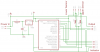
I've been making a lot of changes to the circuit, so the drawings I may have attached to this thread no longer apply. one of the main changes is to move the flasher from the indicator circuit to the main circuit leaving only the LEDs and their resistors. but I'm having trouble with the idea of the likelyhood of feedback of +5V back into the 555 via Pin 3, but I put a 1N4148 Diode to block it. Is that a good Idea? I've included the circuit as it stands now, even though I may end of changing it as I get ideas.
 

Attachments

  • control circuit.png
    control circuit.png
    44.2 KB · Views: 166
I still havent gotten the code down to get it working like it needs to. I was told on another forum that my initialization code was wrong for the 16F628 and that I was trying to run on an interrupted vector.
 
I've made some changes to the circuit and made Port A input and Port B output. I'm still looking for code that debounces the input. I'm making the changes to the code switching locations for inputs and outputs, so it may be a little while before I can post the code.
 
You should ask how to debounce the switches but we need to know what type of switches are being used.
Are they "push buttons" or "switches" and how often are they pushed.
 
Last edited:
I'm still on working on trying to figure out what kind of switches to use as my upper and lower sensors. I read in different places that you can debounce switches from within the code. I did a search here and got a bunch of results that seems to point to the resistor/capacitor combo or an in-line resistor and also debouncing within code. I'm attaching images of the board and schematic to show the changes I've made to my design and layout.
 

Attachments

  • Control Schematic.png
    Control Schematic.png
    12.1 KB · Views: 162
  • Control Board.png
    Control Board.png
    6.5 KB · Views: 133
Do the debouncing in code, it's mostly a simple delay.

That's what I was thinking of. Where would I put the call to the delay subroutine in the code when I want to debounce the inputs? Would it be just after the inputs are scanned or further down after the action code? I'm thinking just after the inputs are scanned.
 
Rather than insert a delay, you "poll" the inputs and use a register as a "flag file" to detect the condition of the switch(es). This allows you to use a display at a later date and not create any flashing on the display.
 
Rather than insert a delay, you "poll" the inputs and use a register as a "flag file" to detect the condition of the switch(es). This allows you to use a display at a later date and not create any flashing on the display.

What do I need to do to poll the inputs? I've looked at a several sites that didn't even cover that in their tutorials. Give me a brief sample and I'll go from there trying to fix my code.
 
Status
Not open for further replies.

Latest threads

Back
Top