Continue to Site

Welcome to our site!

Electro Tech is an online community (with over 170,000 members) who enjoy talking about and building electronic circuits, projects and gadgets. To participate you need to register. Registration is free. Click here to register now.

  • Welcome to our site! Electro Tech is an online community (with over 170,000 members) who enjoy talking about and building electronic circuits, projects and gadgets. To participate you need to register. Registration is free. Click here to register now.

pic programer

Status
Not open for further replies.

Gaston

Member
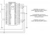
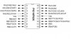
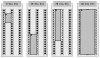
hello nigel , i am building the programing boaed on your web site. i am useing the 40 pin zif. i am going to be useing the 18 pin pic. my question is do i need to wire it any different for the 18 pin chip. the reason i ask is because none of the vss or vcc pins line up with the 18 pin pic
 
you dont need to wire it any different for the 18-pin PIC. just use a 40-pin ZIF socket and place the PICs as mentioned in the schematic of the ozipic'er programmer. for an 18-pin PIC you will have to place it on the bottom of your socket. that means that VDD, VPP, VSS, RB6 and RB7 will be in contact with the programmer and thats all you need to program the PIC.

i hope that helps
 

Attachments

  • programmer.jpg
    programmer.jpg
    39 KB · Views: 1,328
  • f628.jpg
    f628.jpg
    37.9 KB · Views: 1,310
Gaston said:
mabey im reading this wrong https://www.electro-tech-online.com/custompdfs/2005/04/p16pro40-2.pdf
it says to put the 18 pi pic at the bottom with pin 9 on pin 20 . it would make sense if you put pin 1 on pin 1 .is this a tyepographical eror??

The whole point of the P16PRO40 is that you can fit any DIL PIC into the same 40 pin Aries ZIF socket. As such, different size ones fit in different places, bear in mind it's not just a question of connecting the correct pins, but of NOT connecting the wrong pins!.

This is also the reason the P16PRO40 has two Vpp lines (Vpp and Vpp40), with Vpp40 being used for 40 and 28 pin devices, and Vpp for the others.

As a matter of interest, you can fit 14 pin devices where the 8 pin one is supposed to go.
 
If you ignore the middle single-inline socket column in the drawing below you'll see how the different size PICs would be inserted into a 40-pin ZIF socket on the P16PRO40...

I apologize if this drawing makes things more confusing -- it was my attempt some time ago at a flexible printed circuit board socket scheme that would allow the use of three 20-pin single-inline sockets or an expensive 40-pin ZIF socket...

Regards, Mike
 

Attachments

  • p16pro40_sockets.jpg
    p16pro40_sockets.jpg
    49.6 KB · Views: 1,349
thanks guys. i see it now. i can't believe i couldn't see it last night. that just proves the effects of fatigue.
 
Puggs said:
Just as a matter of interest, i downloaded the software for this hardware http://www.picall.com it said on the site it doesn't need to be registered, but it keeps telling me it's unregistered... will it still work...

It only works for a limited number of devices, or a limited memory range.

My software WinPicprog works fine with it, as does IC-Prog.
 
i notice that pin 1 on the 40 pin zif isnt shared with any other for the 18 pin pic. does the 18 pin not use that one?
 
Gaston said:
i notice that pin 1 on the 40 pin zif isnt shared with any other for the 18 pin pic. does the 18 pin not use that one?

You've already been told which ones it uses! - so why ask again?.

It's not just a question of using an empty pin, but of none of the other used pins affecting the device you're trying to program - you DON'T want to stick 13V on an I/O pin!.
 
im sorry but this is new to me. i have never fooled with a microcontroler before. some times when something is really new and different it is like trying to undo a knot to learn. but the more you learn and understand the easier it gets. i see what your talking about now.
 
Status
Not open for further replies.

Latest threads

Back
Top