Continue to Site

Welcome to our site!

Electro Tech is an online community (with over 170,000 members) who enjoy talking about and building electronic circuits, projects and gadgets. To participate you need to register. Registration is free. Click here to register now.

  • Welcome to our site! Electro Tech is an online community (with over 170,000 members) who enjoy talking about and building electronic circuits, projects and gadgets. To participate you need to register. Registration is free. Click here to register now.

pic problem or stupidity

Status
Not open for further replies.

Lighty

New Member
Hi All

Been trying to teach myself on how to program pics, I built mysef a serial "JDM" programmer and used PICPgm software to program the pic, code was compiled on Proton IDE Lite (PICBasic) as I found it easy.

I wrote a really basic program just to test, just making 2 LEDs flash.....but it doesn't seem to work, what I do know is, Proton only has the 16F628A listed on the program and I'm using a 16F826, not the "A".

When I program it with PICPgm, it does "verifies" and say completed and doesn't show any errors.

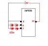
But when running it on my test board it doesn't work..... just have 2x 3mm LED in series from RB0 and RB1...

Quote

Device = 16F628A 'This tells the compiler what microcontroller we are using.

XTAL = 4 'This tells the compiler how fast the chip will be running, which in this case is 4MHz.

Symbol LED0 = PORTB.0 'This is an "alias", a way of naming things to make them more convenient to work with. Here we are setting
Symbol LED1 = PORTB.1 ' up PORTB.0 to have the name "LED"; now when we use the name "LED" in the program the compiler will know
' we mean PORTB.0. It is just an easier way of remembering things, as you'll see later.


TRISB = %00000000 ' Sets pins/port to outputs

Flasher:

High LED0 'flash LED0
DelayMS 200
Low LED0
DelayMS 350

High LED0 'flash LED0
DelayMS 200
Low LED0
DelayMS 350

High LED0 'flash LED0
DelayMS 200
Low LED0
DelayMS 350

High LED0 'flash LED0
DelayMS 200
Low LED0
DelayMS 350


High LED1 'flash LED1
DelayMS 200
Low LED1
DelayMS 350

High LED1 'flash LED1
DelayMS 200
Low LED1
DelayMS 350

High LED1 'flash LED1
DelayMS 200
Low LED1
DelayMS 350

High LED1 'flash LED1
DelayMS 200
Low LED1
DelayMS 350


GoTo Flasher

****** sorry, don't know how to post the "code" in this text box:eek:
 
Assuming you want to use the internal OSC, try to add those line at the top of your code
Code:
    REMINDERS = FALSE
    Config      INTRC_OSC_NOCLKOUT,_ ' Internal Oscillator
                WDT_ON,_             ' Enable watch dog timer
                PWRTE_ON,_           ' Enable power up timer
                MCLRE_ON,_           ' Enable MCLR pin
                BODEN_ON,_           ' Enable brown out detect
                LVP_OFF,_            ' Disable Low voltage programming mode   
                DATA_CP_OFF,_        ' Disable data code protect
                CP_OFF               ' Disable code protect
    REMINDERS = TRUE
    WATCHDOG  = On

To post your code like above, you need to use the code tags

[CODE]
Then paste your code here
[/CODE]
 
Last edited by a moderator:
Well one can only suspect that the configuration registers have changed between the 16f628 and the 16f628A devices. Unless the lite version supports the non "A" version configuration bits? you are out of luck.

Try to see if any of the other commercial compilers support your device in their free/demo/lite versions. If not, then GCBasic will work, and is a free beer license.
 
Assuming you want to use the internal OSC, try to add those line at the top of your code
Code:
    REMINDERS = FALSE
    Config      INTRC_OSC_NOCLKOUT,_ ' Internal Oscillator
                WDT_ON,_             ' Enable watch dog timer
                PWRTE_ON,_           ' Enable power up timer
                MCLRE_ON,_           ' Enable MCLR pin
                BODEN_ON,_           ' Enable brown out detect
                LVP_OFF,_            ' Disable Low voltage programming mode   
                DATA_CP_OFF,_        ' Disable data code protect
                CP_OFF               ' Disable code protect
    REMINDERS = TRUE
    WATCHDOG  = On

To post your code like above, you need to use the code tags

[CODE]
Then paste your code here
[/CODE]

Thanks mister_e,

Thats correct, wanting to use internal OSC. copied that code into my compiler but it didn't reconise it, but manage to find the following...


Code:
Device = 16F628A       'This tells the compiler what microcontroller we are using.


XTAL = 4               'This tells the compiler how fast the chip will be running, which in this case is 4MHz.

Symbol NOT_BOD = PCON.0 ' Brown-out Reset Status Flag
Symbol NOT_POR = PCON.1 ' Power-on Reset Status Flag
Symbol OSCF = PCON.3    ' INTRC/ER oscillator speed
Symbol PGM = PORTB.4   ' Low voltage programming pin
Symbol LED0 = PORTB.0  'This is an "alias", a way of naming things to make them more convenient to work with.  Here we are setting 
Symbol LED1 = PORTB.1  '   up PORTB.0 to have the name "LED"; now when we use the name "LED" in the program the compiler will know 
                       '   we mean PORTB.0.  It is just an easier way of remembering things, as you'll see later.
                       
TRISB = %00000000       ' Sets pins/port to outputs
												
flasher:

[COLOR="Red"]Pattern Program continues[/COLOR]

The test circuit attached. (sorry, I know its bad)

please help, where am I going wrong?:mad:
 

Attachments

  • PIC.JPG
    PIC.JPG
    15.8 KB · Views: 419
Last edited by a moderator:
Nope, this will not do anything with the configuration fuses. You could still try to set them manually in your device programmer software. One thing for sure, the example I provided compiled fine here. Not sure if this could be yet another limitation of their Demo Version...

Finger cross, probably the .HEX file will never work for the non A 16F628 version anyways.

EDIT: wait a minute, is it really PIC16F826 or PIC16F628 you have in your hand?
 
Last edited:
configuration fuses ???? :confused:

PIC is the 16F628

I Just down loaded GCBasic, will try compile with it, just that I need something easy as I have had not experience with pics prigramming before.:eek:
 
Ok, tried GCBasic, don't understand it, is there any other software that works in the same "language" as the Proton IDE Lite? something I can understand.
 
Well most Basic languages are easy enough to understand,.... given time. It is always difficult to get the first few programs under way, no matter which language, which compiler. One missed configuration line, misplaced or missing "," ".", ";", "{", "}", and it's a no go, very unforgiving in terms of syntax.

Not saying GCBasic is for you, or anyone else, only an option, and it supports your 16f628. So will provide a blinky led example for your 16f628 based on your previous code. Here were my instructions for using GCBasic and AdamSoft on his recent "Which PIC?" post.

Yes you can import the compiled.asm or yourfile.asm to a MPLAB project if you wish. Or better yet just import the compiled.hex directly to the Pickit 2, clone, or? programmer. With the auto import hex feature of the Pickit 2, you have a one button to download sequence.

Here is some code for GCBasic, if you want to flash some leds on your 10F206. One could just paste into notepad, or any other editor, save to the GCBasic directory, drag and drop on COMPILE.BAT, then import the compiled.hex to your programmer. A good editor program with a macro function is the best way to go to automate the process and keep your files organized.
Code:
#chip 16f628, 4 
#config INTRC_OSC	

#define LED1 PortB.0
#define LED2 PortB.1
dir LED1 out
dir LED2 out 

Main: 
SET LED1 ON 
SET LED2 OFF 
WAIT 50 10ms 
SET LED1 OFF 
SET LED2 ON 
WAIT 50 10ms 
goto Main
 
Last edited:
Thanks Nickelflipper!

As I said, I've never done this before, so teaching myself is quite frustrating to say the least, thx for you example, but have a few Qs...

Code:
#chip 16f628, 4              [COLOR="Red"]tells programmer what chip is being used, and the 4 is for the frequency, correct?[/COLOR]
#config INTRC_OSC	 [COLOR="Red"]tells the pic to use internal OSC?[/COLOR]

#define LED1 PortB.0     [COLOR="Red"]defines name "LED1" to portb.0? why the #?[/COLOR]
#define LED2 PortB.1
dir LED1 out   [COLOR="Red"]makes output (bit??) low?[/COLOR]
dir LED2 out 

Main: 
SET LED1 ON 
SET LED2 OFF 
WAIT 50 10ms   [COLOR="Red"]why 50 & 10? 50 to 1st line and 10 to 2nd line???[/COLOR]
SET LED1 OFF 
SET LED2 ON 
WAIT 50 10ms 
goto Main
 
Code:
#chip 16f628, 4              [COLOR="Red"]tells programmer what chip is being used, and the 4 is for the frequency, correct?[/COLOR]
Yes

Code:
#config INTRC_OSC	 [COLOR="Red"]tells the pic to use internal OSC?[/COLOR]
Yes

Code:
#define LED1 PortB.0     [COLOR="Red"]defines name "LED1" to portb.0? why the #?[/COLOR]
yes, kinda fancy syntax ;) Probably to identify the Compiler directive

Code:
#define LED2 PortB.1
dir LED1 out   [COLOR="Red"]makes output (bit??) low?[/COLOR]
yes/no, let's say it configure the LED1 pin as an output. It doesn't assign a logic level yet.

Code:
WAIT 50 10ms   [COLOR="Red"]why 50 & 10? 50 to 1st line and 10 to 2nd line???[/COLOR]
Stands for 50x10mSec, so 500mSec

I don't know GCBasic, never used it myself, I found the info on their online help
Great Cow BASIC Help
 
Last edited:
Code:
#define LED1 PortB.0     [COLOR="Red"]defines name "LED1" to portb.0? why the #?[/COLOR]
yes, kinda fancy syntax ;) Probably to identify the Compiler directive

Ok, must just remember:(

Code:
#define LED2 PortB.1
dir LED1 out   [COLOR="Red"]makes output (bit??) low?[/COLOR]
yes/no, let's say it configure the LED1 pin as an output. It doesn't assign a logic level yet.

:eek: should've know this one.... same as TRISB?

Code:
WAIT 50 10ms   [COLOR="Red"]why 50 & 10? 50 to 1st line and 10 to 2nd line???[/COLOR]
Stands for 50x10mSec, so 500mSec

stupid Q, but why 50x10? can't we just say 500? maybe something to do with OSC speed?

I don't know GCBasic, never used it myself, I found the info on their online help
Great Cow BASIC Help

Thanks will check it out?

Does MPLAB IDE V6.61 support this code/language?

Thanks for everyones help, starting to see a bit of light at the end of the tunnel:D
 
Last edited:
Presuming from your reply, it worked?

Fair enough, no comments in the supplied code. Tend to leave out on the most basic of programs, but perhaps not so intuitive for the beginner.

Well mister_e pretty much nailed it on the code part. The #define uses the ability of an assembler preprocessor to link/alias a shorthand name/symbol for a port,pin or even a statement like:

#define waitLCD wait 10 ms
or
#define LED1on Set PortB.0 On

To begin to understand any new language or compiler, there is usually a tutorial or help file hanging around. In the case of GCBasic there are two very similar help files; one is in the online help tab of the GCBasic website, and the other is in the GCBasic dir/GCBasic.chm file. The one in the GCBasic directory is a little more up to date, and includes the "on interrupt" command syntax. Check out the getting started tab, and read the very first topics of the online help, like PIC Crash Course. Further down you will see the dir, wait, #chiip, #config, and #define compiler directives etc.

Using a high level language like Basic or C or? will hide some of the complexities of assembly language. The behind the scenes compiler functions can be a good or bad thing, depending on your perspective or objectives.
 
Nickelflippr

I haven't yet tried it, as my laptop doesn't have a serial port to program:mad:

will hopefully be able to get on a PC with a port tomorrow, but will keep on reading the "help" for now, and just compile as I learn....

why does the "WAIT 50 10ms", could we not just write WAIT 500ms?
 
Nickelflippr

I haven't yet tried it, as my laptop doesn't have a serial port to program:mad:

will hopefully be able to get on a PC with a port tomorrow, but will keep on reading the "help" for now, and just compile as I learn....

why does the "WAIT 50 10ms", could we not just write WAIT 500ms?

Does MPLAB IDE V6.61 support this code/language?

Sooner or later the programmer thing will come up, get a Pickit 2, or BlueRoom's Junebug clone, when feasible.

Haven't looked lately, but the wait us, and wait ms may very well accept word size variables (not documented in help), be sure to declare any word size variables if you do. The 10ms, 10us wait states may look a little weird alright, but handy. Like if working with servo code, "wait 175 10us" will give an integer 1.75ms without resorting to a word size variable. Using byte size variables is important if you are to be working on the low pin count, and Ram limited PIC's. It will produce a much tighter and more efficient code.

Not sure about V6.61 of MPLAB, its up to V8.3 last time I saw, should work. But yea, you can add the compiled.asm file to the source folder of your MPLAB project. MPLAB will nag you to update the project source file after each "external" recompile. The stopwatch in Simulator can come in handy.
 
thanks chaps,

but now I got a really stupid Q, I've written the code and want to compile it to a hex file to upload it to the PIC, how do I do this with GCBasic, can't find any button/command to do this? Help says to drag and drop a file onto the "compile.bat" file in the home DIR of GCBasic.... there is no file like this......when trying to save it, it doesn't define the .XXX file name???

PLease help!
 
How about a picture:). Cut and paste previous led code into a notepad file, and save as 16f628.txt in the GCBasic dir. Drag and drop the .txt file into the COMPILE.BAT file, GCBasic will now compile, assemble, and produce the "compiled.HEX" file. Import this hex file to your programmer and light up the leds!!!!

Strongly suggest using the Crimson Editor per the tutorial from the GCBasic website. When Crimson editor is set up, then a one button compile process is possible by hitting the macro button (F9 or Ctl + 9). Setting up an editor, or IDE for that matter, will display an output window which gives compiler or assembler errors if encountered in your program;). Very important information to have while debugging.

Don't expect to see a successful build/compile every time, it just doesn't happen. If you stick with it, the rewards await you.

**broken link removed**
 
thx Nickelflippr,

managed to figure it out, copy pasted "SciTE4gcBasic" into a text file, then draged it over the compile.bat file and it worked! but why type it out in the other program just to paste it into a text file?

loaded the hex onto the PIC, and nothing, zip......:mad:

What am I doing wrong????? :mad::eek::mad::eek::mad::eek::mad:

Here is the code from the text file, I know its long for what it is, but just want to get the basics done 1st!

Code:
#chip 16f628, 4
#config INTRC_OSC

#define LED1 PortB.0
#define LED2 PortB.1
dir LED1 out
dir LED2 out

Main:

SET LED1 ON
WAIT 10 10ms
SET LED1 OFF
WAIT 20 10ms

SET LED1 ON
WAIT 10 10ms
SET LED1 OFF
WAIT 20 10ms

SET LED1 ON
WAIT 10 10ms
SET LED1 OFF
WAIT 20 10ms


SET LED2 ON
WAIT 10 10ms
SET LED2 OFF
WAIT 20 10ms

SET LED2 ON
WAIT 10 10ms
SET LED2 OFF
WAIT 20 10ms

SET LED2 ON
WAIT 10 10ms
SET LED2 OFF
WAIT 20 10ms

SET LED1 ON
SET LED2 ON
WAIT 10 10ms
SET LED1 OFF
SET LED2 OFF
WAIT 20 10ms

SET LED1 ON
SET LED2 ON
WAIT 10 10ms
SET LED1 OFF
SET LED2 OFF
WAIT 20 10ms

SET LED1 ON
SET LED2 ON
WAIT 10 10ms
SET LED1 OFF
SET LED2 OFF
WAIT 20 10ms

goto Main


And here is the code from the .ASM file after compiled.

Code:
;Program compiled by Great Cow BASIC (0.9 10/2/2007)
;Need help? See the GCBASIC forums at http://sourceforge.net/forum/?group_id=169286,
;check the documentation or email hconsidine@bigpond.com.

;********************************************************************************

;Set up the assembler options (Chip type, clock source, other bits and pieces)
 LIST p=16F628, r=DEC
#include <P16F628.inc>
 __CONFIG _INTRC_OSC_CLKOUT & _WDT_OFF & _LVP_OFF & _MCLRE_OFF

;********************************************************************************

;Set aside memory locations for variables
DELAYTEMP	equ	32
DELAYTEMP2	equ	33
SysWaitTemp10MS	equ	34
SysWaitTempMS	equ	35

;********************************************************************************

;Jump to initialisation code when PIC is reset
	ORG	0
	call	INITSYS
	goto	SystemInitialise

;********************************************************************************

;Interrupt vector
	ORG	4
	retfie	

;********************************************************************************

;Various initialisation routines, automatically called by GCBASIC
SystemInitialise

;********************************************************************************

;Start of the main program
	banksel	TRISB
	bcf	TRISB,0
	bcf	TRISB,1
MAIN		
	banksel	PORTB
	bsf	PORTB,0
	movlw	10
	movwf	SysWaitTemp10MS
	call	Delay_10MS
	bcf	PORTB,0
	movlw	20
	movwf	SysWaitTemp10MS
	call	Delay_10MS
	bsf	PORTB,0
	movlw	10
	movwf	SysWaitTemp10MS
	call	Delay_10MS
	bcf	PORTB,0
	movlw	20
	movwf	SysWaitTemp10MS
	call	Delay_10MS
	bsf	PORTB,0
	movlw	10
	movwf	SysWaitTemp10MS
	call	Delay_10MS
	bcf	PORTB,0
	movlw	20
	movwf	SysWaitTemp10MS
	call	Delay_10MS
	bsf	PORTB,1
	movlw	10
	movwf	SysWaitTemp10MS
	call	Delay_10MS
	bcf	PORTB,1
	movlw	20
	movwf	SysWaitTemp10MS
	call	Delay_10MS
	bsf	PORTB,1
	movlw	10
	movwf	SysWaitTemp10MS
	call	Delay_10MS
	bcf	PORTB,1
	movlw	20
	movwf	SysWaitTemp10MS
	call	Delay_10MS
	bsf	PORTB,1
	movlw	10
	movwf	SysWaitTemp10MS
	call	Delay_10MS
	bcf	PORTB,1
	movlw	20
	movwf	SysWaitTemp10MS
	call	Delay_10MS
	bsf	PORTB,0
	bsf	PORTB,1
	movlw	10
	movwf	SysWaitTemp10MS
	call	Delay_10MS
	bcf	PORTB,0
	bcf	PORTB,1
	movlw	20
	movwf	SysWaitTemp10MS
	call	Delay_10MS
	bsf	PORTB,0
	bsf	PORTB,1
	movlw	10
	movwf	SysWaitTemp10MS
	call	Delay_10MS
	bcf	PORTB,0
	bcf	PORTB,1
	movlw	20
	movwf	SysWaitTemp10MS
	call	Delay_10MS
	bsf	PORTB,0
	bsf	PORTB,1
	movlw	10
	movwf	SysWaitTemp10MS
	call	Delay_10MS
	bcf	PORTB,0
	bcf	PORTB,1
	movlw	20
	movwf	SysWaitTemp10MS
	call	Delay_10MS
	goto	MAIN
BASPROGRAMEND		
	sleep	
	goto	$
		
;********************************************************************************
;Subroutines included in program
;********************************************************************************
		
DELAY_MS		
DMS_START		
	movlw	10
	movwf	DELAYTEMP2
DMS_OUTER		
	movlw	33
	movwf	DELAYTEMP
DMS_INNER		
	decfsz	DELAYTEMP, F
	goto	DMS_INNER
	decfsz	DELAYTEMP2, F
	goto	DMS_OUTER
	decfsz	SysWaitTempMS, F
	goto	DMS_START
	return	
		
;********************************************************************************
		
Delay_10MS		
D10MS_START		
	movlw	10
	movwf	SysWaitTempMS
	call	Delay_MS
	decfsz	SysWaitTemp10MS, F
	goto	D10MS_START
	return	
		
;********************************************************************************
		
INITSYS		
	clrf	PORTA
	clrf	PORTB
	movlw	7
	movwf	CMCON
	return	
		
;********************************************************************************

 END

Where did I go wrong?
 
one other thing regarding GCBasic....

When I 1st downloaded "GCbasic" I landed up with a program called "SciTE4gcBasic" with an application file called "gcBasicIDE", it opens up like a compliler....... but when I went to go find that compiler.bat file in the folder, there was nothing! so I downloaded GCBasic again from a different link, now i've got that .bat file but there is not application, only a couple DOS based files.... i'm so confused?
 
You are using one the IDE's great, forget about the cut and paste, just trying to get you going with least hassles possible.

Nothing wrong with the code that I can see, so have to look at the hardware. What programmer, and type are you using? Have you successfully programed code into a PIC before using that programmer? Can you see or read hex numbers in the programmer memory window?

Are you breadboarding the PIC, or is it on a development board. Is there a 0.1uf bypass capacitor across the Vdd and Vss of the PIC? Leds in backwards?

Sounds like either failed programming, the oscillator not firing up, or bad, wrong wiring connections.

P.S. not personally using any of the IDE's so cannot comment. Be sure that you have downloaded the latest update.zip from the GCBasic website, if you haven't done so already.
 
Status
Not open for further replies.

Latest threads

New Articles From Microcontroller Tips

Back
Top