Continue to Site

Welcome to our site!

Electro Tech is an online community (with over 170,000 members) who enjoy talking about and building electronic circuits, projects and gadgets. To participate you need to register. Registration is free. Click here to register now.

  • Welcome to our site! Electro Tech is an online community (with over 170,000 members) who enjoy talking about and building electronic circuits, projects and gadgets. To participate you need to register. Registration is free. Click here to register now.

pic problem or stupidity

Status
Not open for further replies.
You are using one the IDE's great, forget about the cut and paste, just trying to get you going with least hassles possible.

cool


Nothing wrong with the code that I can see, so have to look at the hardware. What programmer, and type are you using? JDM type I think, see attached schem of it

Have you successfully programed code into a PIC before using that programmer? no, just built it

Can you see or read hex numbers in the programmer memory window?

Not using the same PC as I do the programming on, but if i load the file using the same software on my laptop, it doesn't show anything, but is this not because the programmer is not connected? but once i've programmed the PIC, I use the "verify" button on the software, PICPgm, and it says its ok?

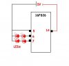
Are you breadboarding the PIC, or is it on a development board. Is there a 0.1uf bypass capacitor across the Vdd and Vss of the PIC? Leds in backwards?

Breadboard, as per schem

Sounds like either failed programming, the oscillator not firing up, or bad, wrong wiring connections.

the wiring is right I'm sure, see attached pic.

P.S. not personally using any of the IDE's so cannot comment. Be sure that you have downloaded the latest update.zip from the GCBasic website, if you haven't done so already.

copied from the "release notes" txt in one of its folders - "Great Cow Basic Alpha 0.8.5.0 17/6/2006"

might be old????
 

Attachments

  • PIC.JPG
    PIC.JPG
    15.8 KB · Views: 212
  • pic-pg1-sch.gif
    pic-pg1-sch.gif
    8.3 KB · Views: 278
ughh, ......just search the posts in this forum about JDM programmers to read the tales of woe.

Download the aforementioned zip file and copy into the GCBasic dir anyway. It will have improvements, since the 9.30 version was created awhile ago.

Yep, leds in backwards per schematic. Realize if you swap them around they will be in a common anode configuration, and the PIC port pin will need to be low or off to light it.

The other way is to leave the leds as they are, but route your led common cathodes to ground instead of the 5V positive per schematic. Use 1 led and a 330 ohm resistor per pin to limit current. Have never killed an led by flip flopping around on 5v supply, so easy to double check polarity.

Install 0.1uf capacitor across Vdd and Vss as near to the PIC as possible!! If that's an unregulated battery supply, putting a 100uf filter cap across Vdd and Vss wouldn't hurt either.

Good luck.
 
ughh, ......just search the posts in this forum about JDM programmers to read the tales of woe.

Download the aforementioned zip file and copy into the GCBasic dir anyway. It will have improvements, since the 9.30 version was created awhile ago.

Busy downloading!

Yep, leds in backwards per schematic. Realize if you swap them around they will be in a common anode configuration, and the PIC port pin will need to be low or off to light it.

ugghhh.... when output pin high, does it not "supply" the 5V?


The other way is to leave the leds as they are, but route your led common cathodes to ground instead of the 5V positive per schematic. This is how its done, must've drawn the schem wrong...:eek:

Use 1 led and a 330 ohm resistor per pin to limit current. Have never killed an led by flip flopping around on 5v supply, so easy to double check polarity.

will remove the 2nd LED and add 330 ohm resister


Install 0.1uf capacitor across Vdd and Vss as near to the PIC as possible!! If that's an unregulated battery supply, putting a 100uf filter cap across Vdd and Vss wouldn't hurt either.

Good luck.

Using a 7805 with 100uf either side, but will add another across Vss and Vdd.
 
Using a 7805 with 100uf either side, but will add another across Vss and Vdd.
Not necessary to add another.

Remember this?
Sounds like either failed programming, the oscillator not firing up, or bad, wrong wiring connections.
Well, a look into the chipdata folder file in the GCBasic dir, for the 16f628 revealed a startling omission. The top [ChipData] header says IntOsc=0...:mad::mad::mad:!!!!! Darn it. Make that IntOsc=4 and save it.

Also using #config _INTRC_OSC_NOCLKOUT :eek: would be the proper way to config the intosc for i/o functions on the OSCx pins.
 
See what you mean....

so if I understand correct:
Code:
;Set up the assembler options (Chip type, clock source, other bits and pieces)
 LIST p=16F628, r=DEC
#include <P16F628.inc>
 __CONFIG _INTRC_OSC_CLKOUT & _WDT_OFF & _LVP_OFF & _MCLRE_OFF

the "#include <P16F628.inc>" part means it must include the "setup" from that data file? and hence the clock was set at "0", it would not fire up the OSC? so its not taking the "4" front the setup in the writen "text" file..... hope that makes sence
 
ok, compiled it again after editing the data file, loaded it up into "WPicProg16" and used the "disassemble" button, here's what it shows,

Code:
; Generated by WinDis84, (c) Nigel Goodwin 1998.

            LIST      P=16C84, F=INHX8M
            include "P16CXX.inc"
            ORG     0x0000

            CALL    Label_0001
            GOTO    Label_0002
            ORG     0x0004
Label_0002  BSF     STATUS    , RP0
            BCF     STATUS    , RP1
            BCF     TRISB     , 00
            BCF     TRISB     , 01
Label_0004  BCF     STATUS    , RP0
            BCF     STATUS    , RP1
            BSF     PORTB     , 00
            MOVLW   0x0A
            MOVWF   0x24
            CALL    Label_0003
            BCF     PORTB     , 00
            MOVLW   0x14
            MOVWF   0x24
            CALL    Label_0003
            BSF     PORTB     , 00
            MOVLW   0x0A
            MOVWF   0x24
            CALL    Label_0003
            BCF     PORTB     , 00
            MOVLW   0x14
            MOVWF   0x24
            CALL    Label_0003
            BSF     PORTB     , 00
            MOVLW   0x0A
            MOVWF   0x24
            CALL    Label_0003
            BCF     PORTB     , 00
            MOVLW   0x14
            MOVWF   0x24
            CALL    Label_0003
            BSF     PORTB     , 01
            MOVLW   0x0A
            MOVWF   0x24
            CALL    Label_0003
            BCF     PORTB     , 01
            MOVLW   0x14
            MOVWF   0x24
            CALL    Label_0003
            BSF     PORTB     , 01
            MOVLW   0x0A
            MOVWF   0x24
            CALL    Label_0003
            BCF     PORTB     , 01
            MOVLW   0x14
            MOVWF   0x24
            CALL    Label_0003
            BSF     PORTB     , 01
            MOVLW   0x0A
            MOVWF   0x24
            CALL    Label_0003
            BCF     PORTB     , 01
            MOVLW   0x14
            MOVWF   0x24
            CALL    Label_0003
            BSF     PORTB     , 00
            BSF     PORTB     , 01
            MOVLW   0x0A
            MOVWF   0x24
            CALL    Label_0003
            BCF     PORTB     , 00
            BCF     PORTB     , 01
            MOVLW   0x14
            MOVWF   0x24
            CALL    Label_0003
            GOTO    Label_0004
            SLEEP
Label_0005  GOTO    Label_0005
Label_0003  MOVLW   0x0A
            MOVWF   0x25
            CLRF    0x26
            CALL    Label_0006
            DECFSZ  0x24      , f
            GOTO    Label_0003
            RETURN
Label_0006  INCF    0x26      , f
Label_0009  MOVLW   0x0A
            MOVWF   0x21
Label_0008  MOVLW   0x21
            MOVWF   0x20
Label_0007  DECFSZ  0x20      , f
            GOTO    Label_0007
            DECFSZ  0x21      , f
            GOTO    Label_0008
            DECFSZ  0x25      , f
            GOTO    Label_0009
            DECFSZ  0x26      , f
            GOTO    Label_0009
            RETURN
Label_0001  MOVLW   0x07
            MOVWF   0x1F
            CLRF    PORTA
            CLRF    PORTB
            RETURN
 
            ORG     0x2007
            DATA    0x19
 

            END

Don't see anything about the OSC?
 
also, thinking of piting the bullet and buy on of the following.... which one do you recommend? not much difference in price


Part Number: PG164120 - PICkit 2 Microcontroller Programmer

Delivery :Stock

The PICkit 2 Microcontroller Programmer takes advantage of Microchips Full-Speed USB device, significantly speeding up development programming. Included in this package are the PICkit 2 Programming Software, the MPLAB IDE Software, an A to mini-B USB cable, lessons for programming PICmicro MCUs, and more.


.............................................................................................................................................................................

Part Number: DV164120 - PICkit 2 Starter Kit

Delivery : 4-6 weeks

The PICkit 2 Starter Kit contains a PICkit 2 Microcontroller Programmer and a PICkit 2 Low Pin Count Demo Board containing a PIC16F690 PDIP for getting started with programming baseline and midrange flash microcontrollers. PICkit 2 takes advantage of Microchips Full-Speed USB device, thereby significantly speeding up development programming. The PICkit 2 Low Pin Count Demo Board supports 8-, 14-, and 20-pin PICmicros. In addition to the PIC16F690, the board comes with 4 LEDs, a pushbutton, and a pot. Also included are 12 lessons to help get developers up to speed quickly on programming PICmicro MCUs


...............................................................................................................................................................................

Part Number: DV164121 - PICkit 2 Debug Express

Delivery :~2 weeks


PICkit 2 Debug Express allows in-circuit debugging on selected PICmicro microcontroller units (MCUs). In-circuit debugging allows the designer to run, examine, and modify the program while the PICmicro MCU is embedded in the hardware, thereby assisting the designer in debugging the firmware and hardware together. Debug Express interacts with MPLAB IDE software. Programs can be run, stopped, and single-stepped. One breakpoint can be set and the processor can be reset. Register contents can be examined and modified when the processor is stopped. Debug Express requires MPLAB IDE version 7.40 or later.

...............................................................................................................................................................................

Microchip's ICD2 LE (Limited Edition) DV164015

sorry, but only have link.... **broken link removed**
 
the "#include <P16F628.inc>" part means it must include the "setup" from that data file? and hence the clock was set at "0", it would not fire up the OSC?
O.K. hooked up a 16f648a and programmed your blinky led code with a Pickit 2 and it works great. Tried both settings of INTOSC=0 and then INTOSC=4 in the chipdata file, and it made no difference whatsoever:confused:. It appears that the #config _INT_OSC_NOCLKOUT takes precedence here, despite the include file definition.

Which assembler are you using with GCBasic, GPASM, or MPASM? I am using the Microchip MPASM. The choice is made during setup/install process I believe. Shouldn't make a difference, but sometimes GPASM has a problem. Just recently the GPutils supposedly updated all the PIC devices, so a recent copy should be O.K.
...
...
And,
LIST P=16C84, F=INHX8M
include "P16CXX.inc"
I find the disassembly as a little odd, but maybe that's just a misinterpretation of the device file? Can't say where the oscillator config is located, but would tend to believe the GCBasic compiled.asm file above all else.

...
...
Can't keep up with your posts.

I am a fan of the Pickit 2 programmer with the low pin count starter board, or starter kit. Let's you use 8, 14, and 20pin baseline to midrange devices. Very easy to include a seperate dip socket for the 10f's too:). Others will have their own opinion, with the 18f's of any shape or form being the most popular. I say start with the small ones, then graduate to 18f's when the time comes.

Somewhere one should be able to find a Pickit 2 (starter kit) in stock.
 
Last edited:
THANKS for your help Nickelflippr, I realy do appreciate it!;)

At least I know its not the code then, must be either the programmer hardware or software....... I'll go buy a 16F628 (A) which is supported by Proton IDE lite and program it with that, if tha fails, then i'm sure its the hardware?
 
Although rare, it is possible to send a PIC to its grave.

Get a 12f683, and 10f just for the fun of it, when ordering up the Pickit2 kit.
 
Hi All

I've built this project

8 Channel PWM LED chaser

and have tried programming it using my new PICkit 2. Using the 16F628A MCU.

it says programmed but just doesn't work :mad:

I've even tried using the blinky program, and using the same board, but nothing:mad:

Code:
;Program compiled by Great Cow BASIC (0.9 10/2/2007)
;Need help? See the GCBASIC forums at http://sourceforge.net/forum/?group_id=169286,
;check the documentation or email hconsidine@bigpond.com.

;********************************************************************************

;Set up the assembler options (Chip type, clock source, other bits and pieces)
 LIST p=16F628A, r=DEC
#include <P16F628A.inc>
 __CONFIG _INTRC_OSC_CLKOUT & _WDT_OFF & _LVP_OFF & _MCLRE_OFF

;********************************************************************************

;Set aside memory locations for variables
DELAYTEMP	equ	32
DELAYTEMP2	equ	33
SysWaitTemp10MS	equ	34
SysWaitTempMS	equ	35

;********************************************************************************

;Jump to initialisation code when PIC is reset
	ORG	0
	call	INITSYS
	goto	SystemInitialise

;********************************************************************************

;Interrupt vector
	ORG	4
	retfie	

;********************************************************************************

;Various initialisation routines, automatically called by GCBASIC
SystemInitialise

;********************************************************************************

;Start of the main program
	banksel	TRISB
	bcf	TRISB,0
	bcf	TRISB,1
MAIN		
	banksel	PORTB
	bsf	PORTB,0
	movlw	10
	movwf	SysWaitTemp10MS
	call	Delay_10MS
	bcf	PORTB,0
	movlw	20
	movwf	SysWaitTemp10MS
	call	Delay_10MS
	bsf	PORTB,0
	movlw	10
	movwf	SysWaitTemp10MS
	call	Delay_10MS
	bcf	PORTB,0
	movlw	20
	movwf	SysWaitTemp10MS
	call	Delay_10MS
	bsf	PORTB,0
	movlw	10
	movwf	SysWaitTemp10MS
	call	Delay_10MS
	bcf	PORTB,0
	movlw	20
	movwf	SysWaitTemp10MS
	call	Delay_10MS
	bsf	PORTB,1
	movlw	10
	movwf	SysWaitTemp10MS
	call	Delay_10MS
	bcf	PORTB,1
	movlw	20
	movwf	SysWaitTemp10MS
	call	Delay_10MS
	bsf	PORTB,1
	movlw	10
	movwf	SysWaitTemp10MS
	call	Delay_10MS
	bcf	PORTB,1
	movlw	20
	movwf	SysWaitTemp10MS
	call	Delay_10MS
	bsf	PORTB,1
	movlw	10
	movwf	SysWaitTemp10MS
	call	Delay_10MS
	bcf	PORTB,1
	movlw	20
	movwf	SysWaitTemp10MS
	call	Delay_10MS
	bsf	PORTB,0
	bsf	PORTB,1
	movlw	10
	movwf	SysWaitTemp10MS
	call	Delay_10MS
	bcf	PORTB,0
	bcf	PORTB,1
	movlw	20
	movwf	SysWaitTemp10MS
	call	Delay_10MS
	bsf	PORTB,0
	bsf	PORTB,1
	movlw	10
	movwf	SysWaitTemp10MS
	call	Delay_10MS
	bcf	PORTB,0
	bcf	PORTB,1
	movlw	20
	movwf	SysWaitTemp10MS
	call	Delay_10MS
	bsf	PORTB,0
	bsf	PORTB,1
	movlw	10
	movwf	SysWaitTemp10MS
	call	Delay_10MS
	bcf	PORTB,0
	bcf	PORTB,1
	movlw	20
	movwf	SysWaitTemp10MS
	call	Delay_10MS
	goto	MAIN
BASPROGRAMEND		
	sleep	
	goto	$
		
;********************************************************************************
;Subroutines included in program
;********************************************************************************
		
DELAY_MS		
DMS_START		
	movlw	10
	movwf	DELAYTEMP2
DMS_OUTER		
	movlw	33
	movwf	DELAYTEMP
DMS_INNER		
	decfsz	DELAYTEMP, F
	goto	DMS_INNER
	decfsz	DELAYTEMP2, F
	goto	DMS_OUTER
	decfsz	SysWaitTempMS, F
	goto	DMS_START
	return	
		
;********************************************************************************
		
Delay_10MS		
D10MS_START		
	movlw	10
	movwf	SysWaitTempMS
	call	Delay_MS
	decfsz	SysWaitTemp10MS, F
	goto	D10MS_START
	return	
		
;********************************************************************************
		
INITSYS		
	clrf	PORTA
	clrf	PORTB
	movlw	7
	movwf	CMCON
	return	
		
;********************************************************************************

 END
 
Sorry, forgot to mention that that when programming using the PICkit 2 software v2.61 is says "programming failed at program memory 0x000000
 
Status
Not open for further replies.

Latest threads

Back
Top