Hi everyone,
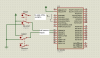
Iam doing a final year project on Swithed reluctance Motor. to explain in a simple way it is basically a motor where in there are 4 phases in the stator and the rotor is made of magnetic material which gets attracted to the stator when the corresponding phase is excited (much like Steper motor). The phase to be excited depends on the position of rotor which is understood from 2 hall sensors. There was 4 phases in the motor I used. Here is the code I used on a 18F452 in C18
#include<p18f452.h>
#pragma config WDT=OFF
#pragma config OSC=HSPLL
#pragma config LVP = OFF
#pragma config PWRT = OFF
void main()
{
TRISB=0x03;//two inputs to understand the current position of the rotor
TRISA=0x00;
PORTA=0x00;
PORTB=0x00;
while(1)
{
if(PORTB==0x00)//for 4 different conditions of hall sensors the phase to be excited is
PORTA=0x09; //according to this loop.
else if(PORTB==0x01)
PORTA=0x0C;
else if(PORTB==0x03)
PORTA=0x06;
else if(PORTB==0x02)
PORTA=0x03;
}
}
The pgm works fine when the machine is on No load, the outputs are given corresponding to inputs and the motor rotates and the speed increases with increase in voltage being applied.
The mystery is when i try to load the machine using the same program, the pic does give output at the beginning but simply fails and stops giving output after a particular voltage. The motor fails to start.
The thing is the input to the motor which are the hall sensors is no way affected by the loading and I do not understand what is happening.
Please do help me guys
PS:when supply to PIC is made off and on again, PIC resumes to give output
Last edited: