Continue to Site

Welcome to our site!

Electro Tech is an online community (with over 170,000 members) who enjoy talking about and building electronic circuits, projects and gadgets. To participate you need to register. Registration is free. Click here to register now.

  • Welcome to our site! Electro Tech is an online community (with over 170,000 members) who enjoy talking about and building electronic circuits, projects and gadgets. To participate you need to register. Registration is free. Click here to register now.

PIC Mosfet Drive

Status
Not open for further replies.

Suraj143

Active Member
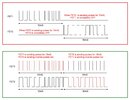
I'm making an 12VDC to 230V AC inverter design using PIC. Before connecting to FETs I measured the PWM outputs through a RC filter.I get 3V peak to peak sine wave.

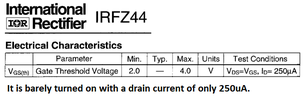
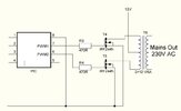
My problem is Can I drive FETs (IRFZ44N / IRF3205) with such small 3V logic levels? How to drive it properly?I'm planing to put 2 pairs of FETs in push pull stage.
 

Attachments

  • Inv_Mosfet.JPG
    Inv_Mosfet.JPG
    38 KB · Views: 232
Both MOSFETs require closer to 10V to be fully on. With 3 to 4 V, they will be in transition, and not have as low a RDSon as expected, causing lots of heat (likely).
You may have to put in an intermediate stage to drive the gates to a full 10V. Also, you may want some resistance from gate to ground, to allow the gate charge to drop (depends on how the input discharges the gate). This also depends on frequency of the on/off transitions
Very Good info Thanks.Just thinking on level conversion stage.Has to do with commonly available parts.
 
A simple discrete version would be an PNP (BC847?) to turn on the MOSFET from the 12V supply but it would be held on by the protection diodes so you'd need an additional NPN to drive the base of the PNP. Or maybe a 9V zener in series with the PNP's base resistor might work.

Mike.
 
Just do it with discrete components, here's what I'm using, it's for a high driver, for a low side one move the top end of R13 to 0V and reverse D1. As another option I tried a proper FET driver IC, which worked fine, but no better than this.

FET_Driver.png
 
Thanks Nigel & Others.

My main target is to run a 230V AC standing fan (60W) from a 12V battery.

What will be a good design?
1)Push pull sine wave inverter (without feedback, but xtal locked,20 steps per cycle)
2)Basic modified sine wave..!!
 
The datasheet of the IRFZ44 Mosfet shows that it needs a Vgs of 10V but an IRLZ44 needs only 4V.

You said the PIC produces a sinewave then you said logic levels. If you use sinewaves or low frequency stepped sinewaves then the Mosfets will be linear and produce a massive amount of heat causing the battery to discharge soon. Use squarewave logic levels for very low heating.

If you use a high frequency oscillator and transformer then you can use PWM to make stepped low frequency sinewaves and the Mosfets will operate with a low amount of heating.
 
I always think of Vgs(th) to be the value at which it will be fully off if just slightly lower. Also, the point where it will be minimally turned on and produce lots of heat, smoke and maybe even flames.:)

Mike.
 
The datasheet of the IRFZ44 Mosfet shows that it needs a Vgs of 10V but an IRLZ44 needs only 4V.

You said the PIC produces a sinewave then you said logic levels. If you use sinewaves or low frequency stepped sinewaves then the Mosfets will be linear and produce a massive amount of heat causing the battery to discharge soon. Use squarewave logic levels for very low heating.

If you use a high frequency oscillator and transformer then you can use PWM to make stepped low frequency sinewaves and the Mosfets will operate with a low amount of heating.
Very usefull info.Thanks

Finally I'm going to send SPWM signal on a push pull design.I have some doubts.

I'm using center tapped transformer & two FETs push pull arrangment.

1)
In a SPWM push pull design do I need to send PWM pulses on the 1st FET & the other 2nd FET remains OFF for 10mS time perriod.On the next 10mS, 2nd FET is sending PWM pulses & the other 1st FET remains OFF. Is this correct?
or
2)
1st FET sends PWM signal, but 2nd FET is doing inverse pulse too in the same time. Is this correct?

Please see my drawing..!!
 

Attachments

  • waveform.JPG
    waveform.JPG
    143.6 KB · Views: 196
Last edited:
The Vgs(th) is the gate voltage that barely begins to turn it on. Its drain current is only 250 micro Amps.
 

Attachments

  • IRFZ44.png
    IRFZ44.png
    24.7 KB · Views: 199
Just do it with discrete components, here's what I'm using, it's for a high driver, for a low side one move the top end of R13 to 0V and reverse D1. As another option I tried a proper FET driver IC, which worked fine, but no better than this.
Hi, I made a low side driver circuit.But I get only 4V to FET gate.What I have made wrong here?

1650010756709.png
 
Check the voltage on the base of Q2. I think you'll find it goes from 8V to 12V. So emitter ~7.3V to 11.3V which one of your traces shows.

Mike.
 
S
Check the voltage on the base of Q2. I think you'll find it goes from 8V to 12V. So emitter ~7.3V to 11.3V which one of your traces shows.

Mike.
Doesn't the FET gets fully off? (Near 0V).It stays around 7.3V?Never gets off..!!!My input frfrequency is 50Hz.
 
S

Doesn't the FET gets fully off? (Near 0V).It stays around 7.3V?Never gets off..!!!My input frfrequency is 50Hz.

Why the 1K?, my original circuit used a 680 ohm, and simply because the supply rail was relatively high, with a 12V supply I'm currently using 100 ohm, and a piece of wire would probably be perfectly fine.

And why does no one like the diode across R4 :D

In any case, running at such a low frequency shouldn't be an issue anyway, you'd normally run at a MUCH higher frequency in a switchmode design
 
Status
Not open for further replies.

Latest threads

Back
Top