Continue to Site

Welcome to our site!

Electro Tech is an online community (with over 170,000 members) who enjoy talking about and building electronic circuits, projects and gadgets. To participate you need to register. Registration is free. Click here to register now.

  • Welcome to our site! Electro Tech is an online community (with over 170,000 members) who enjoy talking about and building electronic circuits, projects and gadgets. To participate you need to register. Registration is free. Click here to register now.

pic compiling/programming questions

Status
Not open for further replies.
I have a old one it's P4 2200mhz and usb 1.1 I use it in the shop If you over load it you have to reboot it. Reboot the thing lol
 
Anyway,i use a 9 volt battery/regulator to avoid to reboot the computer now.
My father has no more reason of being angry now(he was furious lol).
 
No...and i dont think that my computer goes in the modern section, its 10 years old.

We had USB trouble with two student laptops at school. The first erased the PICkit2 code. The other port on this machine was OK.

The second failed in the last 2 weeks of school. it would show a VDD error even with a powered target. Both ports on this laptop did so.

No idea what caused either problem.
 
Anyway,i use a 9 volt battery/regulator to avoid to reboot the computer now.
My father has no more reason of being angry now(he was furious lol).

You have never said exactly what you did. I don't see how you could short anything using the starter kit as it comes straight from the factory. It sounded like you were just programming the 16F690 to blink the LEDs on the board. Did you try to solder something to the board?
 
You have never said exactly what you did. I don't see how you could short anything using the starter kit as it comes straight from the factory

On the starter kit, there are the voltage supply and ground pins(for connecting purposes) very very close(3/4 of a mm) and i shorted that up with a resistor leg...

EDIT:

Is 56.3 khz near enough for a 56 khz tsop irsensor?
 
Last edited:
My ir sensor only outputs 1.7 volts(5 volts)...I built it according to goodwin and others tutorials but it does'nt seems to work...What error could it be?
There is no current output on ir receiving.
Is it a common error?
 
Last edited:
All ir module don't work the same. Some have to have a pullup resistor some don't need
it. The best thing to do is get the module working first then hook it to your pic you can hook a led from the output with a resistor 1k to - volts and see if it's working Some modules you have to hook up like this.
 

Attachments

  • IRmod.PNG
    IRmod.PNG
    5 KB · Views: 176
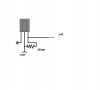
be80be's diagram misses out the supply decoupling resistor, this is pretty crucial,, and it may not work without it.

You need to be aware as well that not all modules have the same pin connections, so you need to make sure it's connected the right way round.
 
be80be's diagram misses out the supply decoupling resistor, this is pretty crucial
I have never used a decoupling resistor the modules I use never would work wired like that I found this a long time ago **broken link removed** And it works for me. But maybe I should of said not wired the same to
All ir module don't work the same.
Only thing is I use a 10k and 4.7uf I think in my drawling I marked the cap a 47uf it should be 4.7uf
 

Attachments

  • Irmod1.PNG
    Irmod1.PNG
    5.8 KB · Views: 166
Last edited:
What electronics store do you go to for parts? There are many in MTL

Addison of course! Never go to active eletronique(they sell 4 330 ohms resistor for 1 $).

The best thing to do is get the module working first then hook it to your pic you can hook a led from the output with a resistor 1k to - volts and see if it's working Some modules you have to hook up like this.

I did exactly like that( to be able to see the led, i had to put the resistor to 330 ohms), but there is still 1.7-8 volts output ...The module works, i pulsed a tsal6200 to 57 khz and the tsop shuts of very well when recceiving the signal. There is no power supply resistor, as it was'nt outputing enough current to see then led.But still 1.7 volts...
 
You can't use the output to source current to an LED, the TSOP has a high value pullup resistor inside (or a small current source). If you're attempting to source current that would explain your problem - however, you can sink current through a TSOP, check my remote control tester at:


Notice that this doesn't have a supply decoupling resistor, but it's only a very crude useage :D
 
Last edited:
Its all right now, it was just my inexperience that made me fail...

I have a pretty strange question. Can a tsop sensor well receive data from ir led underwater?In a clear pool. Or is it simply just a silly idea?

(emitter out of water)
 
Last edited:
Water absorbs infrared light you would have very short range. Read this site some real test with IR **broken link removed**
 
Last edited:
Hey, i just made my two PIC's talk together with a phone:)!
(with ir transmission,TSOP)

After scratching my head i tought: why dont use this design?
It works very great, and that cant be due to any programming error, because there are no wire connecting the two microcontrollers, only air!
After testing, none of the parts where hot :rolleyes: ... so it looks alright, can someone tell me?

https://www.youtube.com/watch?v=hWzqk6A-PIQ&feature=channel_page

Done that, its progress.
 

Attachments

  • why complicate.JPG
    why complicate.JPG
    21.9 KB · Views: 179
Last edited:
Status
Not open for further replies.

Latest threads

Back
Top