Continue to Site

Welcome to our site!

Electro Tech is an online community (with over 170,000 members) who enjoy talking about and building electronic circuits, projects and gadgets. To participate you need to register. Registration is free. Click here to register now.

  • Welcome to our site! Electro Tech is an online community (with over 170,000 members) who enjoy talking about and building electronic circuits, projects and gadgets. To participate you need to register. Registration is free. Click here to register now.

PIC circuit to hold a relay on when input is removed

Status
Not open for further replies.

540itouring

New Member
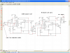
Hi , i need to make a relay timer hold circuit to drive a relay when a input voltage is present but when the input is removed the pic chip will hold the relay on for approx 90 seconds. The 90 second timer part also needs to be reset as soon as the input (trigger signal) is present if this is before the 90 seconds has passed. This project is to detect when a car air conditioning compressor is on and then start the condenser cooling fan but when the compressor cuts out , the cooling fan needs to run for a extra 90 seconds etc to ensure the condenser is cooled . If the compressor cuts in be for 90 seconds the relay must switch the fan on again and 90sec timer reset ready to restart as soon as compressor is switched off. I hope that explains what i need the circuit to do and the cooling fan has its own relay so the second relay which will be driven by this circuit will only switch a max of approx 0.5amps. I was going to use a 555 timer but due to extra capacitors and heat from engine bay i was thinking the timing would vari alot from heat variations etc. I would have liked to use a small pic like a 12c508/9a etc and the circuit will require a input pin to detect 0v/12v and start up with power on in the relay off state unless the 12v input is present. The main part i need help with is a program for a pic which will do the function listed above and i will work the rest out as if i can. I have worked with electronics for many years and can program pics from a asm file after compiling the file to hex. Thanks for all your help in advance.
 
Last edited:
Timer Modules

You can take a look at one of these, I'm sure you can accomplish what you need to to do with a simple timer module:

Altronix: a leading manufacturer of electronics and high technology components

Altronix: a leading manufacturer of electronics and high technology components

**broken link removed**

And if needed, you can always incorporate a ratchet relay into the circuit, controled by one of these timer modules.

Altronix: a leading manufacturer of electronics and high technology components


Hope this helps.
 
If all you want is a timer to run the fan until the condenser is cool enough, there is no need for a good accuracy so a 555 would be fine.

If you are going to use a PIC, use something like a 10F200 or a 12F629 that has an internal oscillator.

For a PIC, you need 5V for the supply, input and output. That needs a voltage regulator for the supply. A couple of resistors can divide the input voltage down to 5 V. For the output, a MOSFET will do, but you should have a freewheel diode if you are driving a relay.
 
Hi , the reason i wanted to use a pic was to try to solve the problem of this...

1 compressor is on and cooling fan them runs
2 compressor cuts out
3 fan needs to run for a good 90 + seconds
4 If compressor cuts back on before 90 seconds , Fan must stay on all the time compressor is on and still run for 90+ seconds when it cuts out again.

I did build a test 555 timer driving a relay but could not get a stable time every time and would not run as listed in my No4 requirement.

No problem to add regulators etc for a pic just need some examples of a code file that i could try and alter values etc for a small chip. I was also thinking of adding this in the case of a larger car relay as some have some electronics in them that can be removed to give extra space. So what i need is help with a code file for a pic with in built osc and also what type the program is for. Then i could build one to experiment with the program. Thanks for your help again
 
Last edited:
I vote for the 555

using a PIC then you get into the problem of voltage regulation. There are voltage regulators made just for automotive use.
A 555 would be less likely to smoke due to the input voltage surgeses etc.
timing is easy. a cross triggered 555 or 556
when timer A starts then timer B starts, Timer B resets timer A
**broken link removed**
use relays, easier to use IMO
been here done that
 

Attachments

  • LM555CrossCancel.GIF
    LM555CrossCancel.GIF
    8.8 KB · Views: 2,009
If I understand the question, the requirement is for a pulse extender that extends the pulse 90 seconds after the input falling edge.

I can't see why a 555 circuit (attached) should have any issues.
 

Attachments

  • EXTENDR.gif
    EXTENDR.gif
    5 KB · Views: 616
The way I understand it is

when the compressor comes on the fan comes on.
AFTER the compressor shuts off the fan runs for 90 seconds longer.
BUT
if the compressor comes back on in that 90 seconds then the 90 second timer is reset.
the timer restarts for 90 again after the compressor shuts off
a retriggiable 555/556 circuit
this is one app where a PIC is not desired due mostly by the automotive electrical system.
one can purchase several 555 timers by the time you buy just one LDR (low drop out regulator.
 
Ok so if i use two 555 timers i would then require two relays instead of one ? . That would take more space than i planed on but could be done but how would the S1 and S2 be triggered ? The switches would be replaced with transistors and a need to know how you would trigger them as it looks like they can not be left shorted and require a quick short and left open.
Any advice on that please. The signal will be 0v / 12v from compressor clutch and the fan control is to just short two wires that control a relay that is already part of the car.


when the compressor comes on the fan comes on.
AFTER the compressor shuts off the fan runs for 90 seconds longer.
BUT
if the compressor comes back on in that 90 seconds then the 90 second timer is reset.
the timer restarts for 90 again after the compressor shuts off
a retriggiable 555/556 circuit
this is one app where a PIC is not desired due mostly by the automotive electrical system.
one can purchase several 555 timers by the time you buy just one LDR (low drop out regulator.
 
you only need one relay

the compressor signals the circuit triggering the first 555 (1/2 of a 556) then it starts the circuit into motion.
the second 1/2 of the 556 controls the relay. The relay can be located in the engine compartment but they do make automotive relays that are really small.
will have to draw a schematic.
 
okthanks for that and will order a 556 to start with. I would like a circuit if you have time and i can start to make the unit. I have a relay that has room for a small pcb inside it so will see how small i can make that once i get a working version. Only other question is how do i pulse the first switch . I would think with a capacitor and transistor . So the compresser voltage triggers the fist 555 and the second 555 drives the relay for 90 secons or if input is held shorted by input volts the second 555 will drive the relay but not timed ? The second 555 only starts timed output as soon as the short accross the first 555 S1 switch is removed ? Does the second switch S2 not get used then ?


the compressor signals the circuit triggering the first 555 (1/2 of a 556) then it starts the circuit into motion.
the second 1/2 of the 556 controls the relay. The relay can be located in the engine compartment but they do make automotive relays that are really small.
will have to draw a schematic.
 
Last edited:
this should get you started

you need to caculate the resistor and capacitor values for 90 seconds.
keep in mind that adding R7 will double the caculated time on.
the compressor enables the reset pin on the first 555 thus the astable outputs a 4.8khz frequency thus triggering the monostable timer.
the capacitorC3 /resistorR3 tied to the base of Q2 keeps the monostable timer triggered.
when the compressor turns off the C3 / R3 makes sure the 90 second timer is triggered.kinda like a missing pulse detector.
be sure to caculate the base resistor R6 (based on the resistance of the relay coil. easy way is a 10 - 1 ratio usually works.
coil = 500 ohm base resistor = 5K
R5 should be calculated as well. I just copied n pasted from another circuit.
you now have some home work to do but this should get you started.
Suggest breadboarding. I tried it out in Multisim and it works but ??
**broken link removed**
 

Attachments

  • Capture7-5-2009-12.39.35 PM.png
    Capture7-5-2009-12.39.35 PM.png
    120.8 KB · Views: 548
I did this with a PIC. Some other features so the PIC was necessary. But later i found out that the wood ducts i built had to be flushed of the 100% humidity after the compressor shut down. Easy to do in the PIC software.

Then I got tired of hearing the SLAP of the fan relay during sleep times. Replaced relay with a Solid State Relay, works like a champ.

Larry
 
Hi , any chance of the info of pic and code you used as i would like to look into what you used if possible. Thanks again for info

I did this with a PIC. Some other features so the PIC was necessary. But later i found out that the wood ducts i built had to be flushed of the 100% humidity after the compressor shut down. Easy to do in the PIC software.

Then I got tired of hearing the SLAP of the fan relay during sleep times. Replaced relay with a Solid State Relay, works like a champ.

Larry
 
As I stated in an earlier post

being the timer is for an automotive use beware that an automotive electrical system is not real friendly towards sensitive electronics = PIC
 
That was such a long time ago, the software is at that site, I am sure.

However, that was long ago, the PIC used was from a bygone era! There are so many new and better PICs today. I am using the PIC16F883 right now, an upgrade from an "876". So much better and powerful PIC. And cheap at Mouser.

In setting up the software, you check the 5 minute timer so the compressor does not turn off and back on without at least the 5 minute delay. Turn on compressor then turn on fan. Wait for thermostat to command off. Turn off compressor then go to delay for the fan. After delay, turn off fan. Sounds simple, huh?

If you want you can shoot me your code for a critique.

Larry
 
I've no idea why you insist on using a pic. If you had a look at the circuit I posted above, you'd see that your task is very simple using a single 555.

Anyway, for a pic12F508, the following code should work. Use MPASM to assemble.
Code:
#include "p12f508.inc"

	__CONFIG _MCLRE_OFF & _WDT_OFF &_IntRC_OSC
	radix dec
	
inpin 	equ 0
outpin 	equ 1
sec90	equ	10
cnta	equ 11
cntb	equ 12
cntc	equ 13

	org 0
start:
	movlw	0
	option
	movlw 	255-(1<<outpin)
	tris 	GPIO
	
main:
	btfsc	GPIO,inpin		; wait for inpin low
	goto	main
	
	call	delay

	btfsc	GPIO,inpin		; make sure inpin is actually low
	goto	main
	
waitloop90:
	bsf		GPIO,outpin		; output high
	
	call	delay
	
	incf	sec90			; 1 second has passed
	btfss	GPIO,inpin
	clrf	sec90			; reset count if inpin is still low
	
	movfw	sec90			; test for 90 seconds past
	xorwf	90
	
	btfss	STATUS,Z		; quit after 90 seconds
	goto	waitloop90		; otherwise keep going
	
	bcf		GPIO,outpin		; reset output
	goto	main
	
; delay for a second
delay:
	movlw	6
	movwf	cntc

dloop0:
	movlw	216
	movwf	cntb
		
dloop1:
	clrf	cnta

dloop2:
	decfsz	cnta
	goto	dloop2

	decfsz	cntb
	goto	dloop1

	decfsz	cntc
	goto	dloop0
	
	retlw 	0

	END
 
Last edited:
He can't see the forrest because

all the trees are in the way
KEEP IT SIMPLE!
use the 555/556 circuit I posted
It works in multisim so it should? work for your app.
BUT learn something
BREAD BOARD the circuit then discover how and why it works.
Your opening yourself up for failure by getting the simple task to complex.
 
I use PICs to improve my programming "skills". The more i work with them, the more macros or canned programs i collect.
I only suggest one way to solve the problem. A 555 is a good simple way to solve the problem. There are other ways depending on what parts you have on hand.
Enjoy the challange!
Larry
 
Status
Not open for further replies.

Latest threads

New Articles From Microcontroller Tips

Back
Top