Continue to Site

Welcome to our site!

Electro Tech is an online community (with over 170,000 members) who enjoy talking about and building electronic circuits, projects and gadgets. To participate you need to register. Registration is free. Click here to register now.

  • Welcome to our site! Electro Tech is an online community (with over 170,000 members) who enjoy talking about and building electronic circuits, projects and gadgets. To participate you need to register. Registration is free. Click here to register now.

Pi network impedance matching

Status
Not open for further replies.

hanhan

Member
Hi,
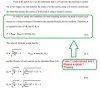
Please help me with these questions about pi network impedance matching. I am reading about "IMPEDANCE Matching" but the book only give formula not much explanation. Therefore, I really need your help.
( I also read many online material about pi network but still got stuck.:eek:)
pi-network-1-modified-jpg.75517

pi-network-2-modified0-jpg.75518
 

Attachments

  • pi network 1(modified).JPG
    pi network 1(modified).JPG
    106.2 KB · Views: 1,352
  • pi network 2 (modified0.JPG
    pi network 2 (modified0.JPG
    135.9 KB · Views: 1,028
Hi,

They seem to be trying to say that the virtual resistor is what the two separated networks see. One sees this as a load the other as a source resistance.

If you remember that the earlier exercises had shown a network that joins a source resistance to a load resistance. In this case the network on the right looks like the load to the network on the left, and the network on the left looks like a source resistance to the network on the right. So they are both satisfied.
However, the drawing of the resistor only makes sense for the network on the left unless we think of the source input voltage being zero for the network on the right.

This should make a lot of sense because we build the network on the left to match the make believe resistor R, and that means we match the source to R perfectly, then we match R to the network on the right so that network matches that R to the output load perfectly. So both networks look like 'R' to each other.

We could analyze this to make sure it is correct of course.


For the Q, isnt that just used to simplify the design procedure? If you show example 4.4 we can take a better look at this too.


The three element network can be formed by adding the two reactances in series into one reactance.
 
Last edited:
Thank you, MrAl.
They seem to be trying to say that the virtual resistor is what the two separated networks see. One sees this as a load the other as a source resistance.

If you remember that the earlier exercises had shown a network that joins a source resistance to a load resistance. In this case the network on the right looks like the load to the network on the left, and the network on the left looks like a source resistance to the network on the right. So they are both satisfied.
However, the drawing of the resistor only makes sense for the network on the left unless we think of the source input voltage being zero for the network on the right.

This should make a lot of sense because we build the network on the left to match the make believe resistor R, and that means we match the source to R perfectly, then we match R to the network on the right so that network matches that R to the output load perfectly. So both networks look like 'R' to each other.
That makes sense. :D I have though about it for two day and haven't found the answer.:eek:
For the Q, isnt that just used to simplify the design procedure? If you show example 4.4 we can take a better look at this too.
Here is the Example 4.4:
example-4-41-jpg.75531

example-4-42-jpg.75532

example-4-43-jpg.75533


Please see the figure 4.19 in my first post.
 

Attachments

  • example 4.41.JPG
    example 4.41.JPG
    140.1 KB · Views: 836
  • example 4.42.JPG
    example 4.42.JPG
    110.7 KB · Views: 1,210
  • example 4.43.JPG
    example 4.43.JPG
    43.8 KB · Views: 832
Hi,
I have found this material. It may be easier to explain. Please help me with this. Thanks.
pi-network-1-1-modified-jpg.75551

pi-network-1-2-modified-jpg.75552

pi-network-1-3-modified-jpg.75553
 

Attachments

  • pi network 1.1 (modified).JPG
    pi network 1.1 (modified).JPG
    68.2 KB · Views: 773
  • pi network 1.2 (modified).JPG
    pi network 1.2 (modified).JPG
    55.3 KB · Views: 827
  • pi network 1.3 (modified).JPG
    pi network 1.3 (modified).JPG
    71.8 KB · Views: 835
Status
Not open for further replies.

Latest threads

New Articles From Microcontroller Tips

Back
Top