Continue to Site

Welcome to our site!

Electro Tech is an online community (with over 170,000 members) who enjoy talking about and building electronic circuits, projects and gadgets. To participate you need to register. Registration is free. Click here to register now.

  • Welcome to our site! Electro Tech is an online community (with over 170,000 members) who enjoy talking about and building electronic circuits, projects and gadgets. To participate you need to register. Registration is free. Click here to register now.

L network impedance-matching circuit

Status
Not open for further replies.

hanhan

Member
Hi,
I am reading about L network in chapter impedance matching. Here is part of the book that I can't understand. Please help me? Thanks.
**broken link removed**
l-network-1-modified-jpg.75489

l-network-2-modified-jpg.75490
 

Attachments

  • L network 1(modified).JPG
    L network 1(modified).JPG
    47.4 KB · Views: 578
  • L network 2(modified).JPG
    L network 2(modified).JPG
    157.7 KB · Views: 540
Last edited:
Hi,

Where is figure 4.4 ?
 
Hi,

That is Fig. 4.5 isnt it? That's what it says it is anyway. Post 4.4 too.
 
Thanks,
Maybe there is a problem in the site. I can see clearly the figure 4.4 at the beginning of my post.
l-network-figure-4-4-jpg.75500

And here is the picture illustrate the end of my post.
l-network-4-jpg.75501
 

Attachments

  • L network figure 4.4.JPG
    L network figure 4.4.JPG
    28.6 KB · Views: 484
  • L network 4.JPG
    L network 4.JPG
    44.2 KB · Views: 544
Hello again,

Wow that's strange. I can see it now. I dont know why it is not visible in the first post. It's still not showing up there. I suspect it has something to do with the way the ads show when not logged in, but i do log in and so i cant be sure what it is.

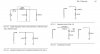
Anyway, if we start with a full analysis of the impedance as seen by the source itself (with it's internal series R), we get:
Z=(s^2*L*C*Rp+Rp+s*L)/(s*C*Rp+1)

Now if we did the design right that would have to equal Rs (the source series resistance) so we set that equal to Z:
Z=Rs
which is:
(s^2*L*C*Rp+Rp+s*L)/(s*C*Rp+1)=Rs

and we can make Rp=a*Rs because the output resistance will be a multiple of Rs. In the case of Rs=100 and Rp=1000, that means a=10.

Now because s is a complex variable we can solve this for L and C, and we get as a result:
C=sqrt(a-1)/(a*w*Rs)
L=(sqrt(a-1)*Rs)/w

So when the impedances are properly matched L is related to C by:
C/L=1/(a*R1^2)

which is another way of saying:
C/L=1/(Rs*Rp)

Now the Q of the RL network is:
xL/Rs

so we have:
Qs=w*L/Rs

and the Q of the RC network is:
Qp=Rp/(1/(w*C))=Rp*w*C

and the impedances are matched when Qs=Qp so that means that:
Qs/Qp=1

So we divide and we get:
C/L=1/(Rs*Rp)

which is exactly what we got from a pure analysis with no assumptions.
 
Thanks a lot, MrAl.:D
Your answer really makes sense. Before asking the question I tried a simple example by two method and that works. However, the second method that uses Q was confusing because I could not prove it.
Your proof bases on a specific circuit (low pass filter). But I think it also works for high pass filter and other topologies of L network.
I am following you method to prove for other arrangements of L network as in figure 4.4.
 
Hello again,

Oh that's good, you'll probably find this interesting. They should all work out.

Also, the A network looks like it is for a low to high impedance transformation while the B network looks like it is for a high to low impedance transformation. Does it say anything about this in your reference material?
That probably means that the C and D networks have this same basic relationship, if true.
 
Status
Not open for further replies.

Latest threads

New Articles From Microcontroller Tips

Back
Top