dinesh4761
New Member
Hello Sir/Madam,
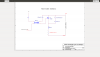
I am engineering student making phase dimmer control using triac
The schematic is as attached
What I have observed that many times attached circuit stop working due to failure of triac
I am not sure is it because of di/dt or dv/dt failure. In order to avoid this I have used triac of much higher rating (10A) even though current needed can be as low as 1A.
However the problem continues.
I have observed that the failure is for transformer powered halogen lamp (inductive load?) and for ceiling fans.
It works satisfactorily for incandescent lamps.
Also I am sharing one more observation that if I connect glass tube fuse link in series with the load then the fuse blows.
From the various information available I realized that I need to use choke / inductor to overcome this problem. Is that right?
I need help to
1. To find out the value of the inductor for 0.5A, 1A and 2A
2. Is this a special type of inductor? if yes wish to know make
Thank you in advance
Dinesh