Continue to Site

Welcome to our site!

Electro Tech is an online community (with over 170,000 members) who enjoy talking about and building electronic circuits, projects and gadgets. To participate you need to register. Registration is free. Click here to register now.

  • Welcome to our site! Electro Tech is an online community (with over 170,000 members) who enjoy talking about and building electronic circuits, projects and gadgets. To participate you need to register. Registration is free. Click here to register now.

Peak Detector without Diode Voltage Drop

Status
Not open for further replies.

krich

New Member
I'm working on a project to quantify the power consumed by an AC device. For my example, let's just assume it's running on a 120V/15A circuit.

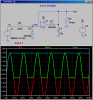
I'm currently working on the current stage of the measurement circuitry. I am using a current transformer with an appropriately sized shunt resistor to give me a 2.5V to -2.5V AC voltage (5V peak to peak). I am using a coupling cap to remove any DC component. My first go at this was to use a 2.5V DC reference to boost the AC signal to a 0V to 5V range so I can measure the waveform with an MCU (in 30mA increments, theoretically). This is where I am at right now. My question is this:

I am not interested in calculating actual power, apparent power, etc, etc. This is not a metering application, rather an application to give a rough magnitude of current (although I wouldn't mind a certain amount of granularity and the project may creep towards metering over time). I figure if I can feed this 2.5V to -2.5V AC signal into a peak detector, not only can I easily measure the peak level with an MCU (PIC/AVR/MSP), but I can also double the resolution by boosting the AC signal to 5V to -5V (10V peak to peak). Most peak detector circuits I have discovered involve a voltage drop of some sort due to the necessity of a diode or two in the circuit. Is there a way to develop a peak detector without the seemingly requisite diodes? An average drop of 0.5V of, say a 1n4001, is quite a large chunk out of my 0-5V range.

Oh, by peak detector, I mean positive peak detector.

I hope my question is clear. I would welcome any suggestions.
 
Here is an rudimentary peak detector (active rectifier).
 

Attachments

  • ActiveRect.png
    ActiveRect.png
    33 KB · Views: 2,152
hi,
A full wave option.
 

Attachments

  • FWPeak1.gif
    FWPeak1.gif
    40.8 KB · Views: 1,954
Thanks guys. These are very similar to the circuits I've seen before. I have not, however, had the fortune to be able to see the circuits simulated as you both have done for me. I do have a question though.

Why would I not see the output voltage reduced by the forward voltage of the diode D1? It is for this reason I have been looking for another solution. Perhaps I have been wrong about this. The simulations are quite clear.

I can see that simulations can prove to be quite educational. I will need to look into that further as well.

Thanks again.
 
...
Why would I not see the output voltage reduced by the forward voltage of the diode D1? ...

Because it is inside the feedback loop of the opamp. Note that the opamp drives the diode so that the voltage at the inverting input matches the peak value of the input voltage.

LTSpice, free download at Linear.com
 
Okay, that makes sense. I've not done a whole lot with opamps yet, so I appreciate the explanation. I can see that this is simply a half-wave rectifier w/ cap version of a peak detector, but by placing an opamp as it is, you don't have to suffer the voltage drop cause by the diode. Smart.

Thanks for the help. I'll be visiting Linear soon.
 
... I've not done a whole lot with opamps yet, so I appreciate the explanation...

Note that the opamp I depicted in the sim should be a modern low-voltage, rail-to-rail input, rail-to-rail output one. A clunky 741 type will not work for this...
 
I would use an MC34072 dual opamp for high frequencies (up to about 30kHz) or MC33172 dual opamp for low frequencies Up to about 12kHz). For very low frequencies (up to about 670Hz) I would use an LM358 dual opamp.
 
Hey guys, I appreciate the help. I have one last series of questions on this:

I was able to load LTspice and run a simulation that matched those you guys provided. Over 0 to 0.1 seconds, the output appears to be constant. However, when simulated over several seconds, it appears to drift downwards to about 200mv under the peak voltage. Is this something that I will see when I build this circuit, or is this simply an issue with the simulation? I will be trying different values based on my needs and hope that I can use the simulator to help move the results closer to what I need. I would like to try to simulate the full wave option to see if it exhibits this issue.

If this is something that needs to be accommodated for in the circuit, would it be reasonable to offset it by adding a little additional gain to the opamp circuit?

Thanks!!
 
Can you show us a snapshot of your circuit and simulation? That droop should not happen.
 
Hey guys, I appreciate the help. I have one last series of questions on this:

I was able to load LTspice and run a simulation that matched those you guys provided. Over 0 to 0.1 seconds, the output appears to be constant. However, when simulated over several seconds, it appears to drift downwards to about 200mv under the peak voltage. Is this something that I will see when I build this circuit, or is this simply an issue with the simulation? I will be trying different values based on my needs and hope that I can use the simulator to help move the results closer to what I need. I would like to try to simulate the full wave option to see if it exhibits this issue.

If this is something that needs to be accommodated for in the circuit, would it be reasonable to offset it by adding a little additional gain to the opamp circuit?

Thanks!!

hi
I dont see any change over 10 seconds.???
 

Attachments

  • AAesp01.gif
    AAesp01.gif
    22.5 KB · Views: 645
Thanks for the ongoing support. I know this is a pretty basic point, but I'm pretty sure it's a fundamental and critical building block that I need to work out.

Here's my results. I just got back home from a business trip, so I'm going to try a few things.

First, I'm going to try a different Opamp in the Spice simulator. Hopefully something more specific to what I have available to me. Next I'm going to try the full wave to see what I get.

EDIT: I tried the Universal OpAmp and I'm getting results more in line with what you guys have been showing.

Next, I need to turn this value into a 10kohm or less impedance for input into the micro. Assuming a simple voltage follower circuit would do the trick. Wow, lots of variables to tweak in this analog circuitry stuff. Pretty neat, but it makes me appreciate even more the on/off nature of digital circuits, of which I have a much better grasp.
 

Attachments

  • peakdetector.PNG
    peakdetector.PNG
    59.2 KB · Views: 822
Last edited:
The problem with your version of the simulation where the output sags is your use of the generic "opamp" (the one without V+ and V- pins). As you have discovered, if you use the more realistic "level.2" universal opamp (with defined V+ and V- pins), the circuit behavior is correct.

The time-constant defined by the 1meg and 10uF capacitor is used to define how slowly the peak bleeds away. If you are feeding this to a PIC A/D input, the capacitor provides the required <10K source impedance for time-varying signals. Don't worry about the 1uA leakage current into the PIC A/D input, the opamp can supply that without even noticing it.
 
Yep, you have confirmed what I have just learned. The cap on the output can provide enough juice to charge the sample cap in the micro.

Been playing with the values of the cap and the bleed resistor to fine tune it to the response I'm looking for. I do want to check out the full wave version of the circuit Eric posted, because I believe that it will allow me to achieve a faster response by bumping the peak twice as fast, allowing me to use a faster decay. Once I figure that out, I guess all that's left is to breadboard a quick circuit to validate with real world inputs and then layout and build the pcb.

Best of all, I can see a clear path forward on my project, and for that I owe you guys. Clearly a debt I likely won't have the skill to repay. Thanks for having the patience to support a highly motivated, and generally ignorant (but getting better), hobbyist.

hi,
Attached FullPeak1.asc for you LTS sims
 

Attachments

  • FullPeak1.asc
    1.8 KB · Views: 362
hi,
A full wave option.

I have been checking voltage readings from a Current Transformer, and it produces between 0V & approx 14V (AC @ 60Hz) which would be the input into the peak detector circuit. Would a LM358 process signals of this amplitude and range, and would I accordingly have to increase the circuit supply voltage in excess of the signal voltage (I was considering a 9V supply).
Alternatively, would it be better practice to consider a shunt resistor across the CT to reduce the voltage by say 50%.
 
Do the 'breadboard' circuits always work, if the circuits test OK in LTSpice?
i.e. how accurately does the simulation follow what happens in a 'real' circuit?
hi,
All the circuits I have simulated in LTS have worked in the real world.
Its important when actually building the circuit on a pcb is to consider careful layout of the components and power rail decoupling.

Which circuit did you have in mind.?

EDIT:
With regard to bread board circuits, if you mean the solder less types where you plug in the components, these are not suitable for some circuit types.
eg: Radio Frequency circuits, Power switching circuits carrying heavy currents or High voltages such as mains supplies.
 
Last edited:
I'm going to build the 'Full Wave Option' which you posted earlier in this thread and feed it into a LM339 comparator chip alongside a reference voltage. The output will eventually drive a relay (I will probably need a transistor to handle the relay current - approx 75mA).
Being new to this, I feel a lot more confident having read your last post - and if I can get the simulation to run, then I stand a good chance that the final circuit will too.

hi,
The MCP6002 [dual] is a rail to rail OPA, and will operate from a 5V supply. Cost 39p GBP
You will need a transistor on the output of a LM393, say a 2N2222 type. [remember a LM393 is open output, so a pull up resistor to 5V is required, say a 3k9]

https://uk.farnell.com/jsp/search/b...ons=false&ref=globalsearch&_requestid=1342043
 
Last edited:
Status
Not open for further replies.

New Articles From Microcontroller Tips

Back
Top