Continue to Site

Welcome to our site!

Electro Tech is an online community (with over 170,000 members) who enjoy talking about and building electronic circuits, projects and gadgets. To participate you need to register. Registration is free. Click here to register now.

  • Welcome to our site! Electro Tech is an online community (with over 170,000 members) who enjoy talking about and building electronic circuits, projects and gadgets. To participate you need to register. Registration is free. Click here to register now.

pcb malfunction

baristini

Member
Hi everyone!

I have a technics keyboard, that when we plug in the only thing it shows it the LCD ilumination.

I made a few measures on power and initial PCB and find every VR are working and power is getting in main PCB.

In this main PCB there is a 32 bit microcontroller MN103002A.

The issue is, how can i make sure this microcontroller is working? Shall i measure VSS and VDD voltages? What is the diference betwenn these 2 voltages ( VSS vs VDD )?

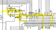
I send in attach block diagram of all circuits ( if anyone have time to watch.. lol ).

Thanks a lot for any help or hint!!
 

Attachments

  • IC04.MN103002A.PDF
    107.1 KB · Views: 129
  • diagramablc.jpg
    3.5 MB · Views: 89
SNS is at fault and will not power on RESET (POR) properly.
This pulls up R2 > Q2 > R4 > RST on p28
But I am not impressed it will hold down RST for a 100 us or so with a dependence on Q2 hFE with R2/R4=100 and an exponential rise. If RST ="1" the voltage must be > 2V.

Calibrate your 10:1 probe and find why you are not getting 4V on SNS There may be a storage cap. missing..
1699726763953.png
 
Last edited:
But be careful SNS comes from line voltage diode bridge that detects line input to pull the RST out of reset slowly then when 3.3V turns on RST goes high quickly by 0.22uF cap C3.
 
ok!! thanks for your help.
when i measure /RST in osciloscope it gets hi imediatly... i dont see any gradient from 0volt...
how can i see if that circuit is working correctly?
 
SNS is at fault and will not power on RESET (POR) properly.
This pulls up R2 > Q2 > R4 > RST on p28
But I am not impressed it will hold down RST for a 100 us or so with a dependence on Q2 hFE with R2/R4=100 and an exponential rise. If RST ="1" the voltage must be > 2V.

Calibrate your 10:1 probe and find why you are not getting 4V on SNS There may be a storage cap. missing..
View attachment 143306
Hi!! Well, dont know why, but i didnt saw this message before....

You mean "SNS" is missing? faulty?

The voltage of RESET in R4 is 2.90v... It shouldnt be? You mean more than 2vols?

I can see that, this checkpoint, i have read with osciloscope, "SNS", goes to pin28 of CN1 ( FAJ BOARD ).

After that, this signal "SNS" goes to MAIN PCB (CN101) and gets the name "E", after that, i cant follow the circuit...
 
Last edited:
Scope SNS
1699817246549.png


Then if OK, Gnd RST carefully to compare the power On RST with this manual RST.
SNS is responsible for holding RST low for some ? microseconds of time, when Vdd rises to 3.3V to turn off RST and over-rides the SNS if high using the PNP transistor to turn off RST.

It might not be working.
 
Last edited:
Well, shorting R4 ( forcing reset ) i see throught RD/WT pin that micro is reseted, this pin goes to 3.3volt 1 or 2 seconds and then goes to 0volt. that is the same that happens when powering on, pin68 (RD/WT) goes high for 1/2 seconds and then goes lo, 0volt... :(

something is making micro goes off... what could be? what tests can i do to find it?
 
find out why from the schematic .

Check 3.3V, Vdd, SNS, RESET, P23 and RST
1699911191929.png
 
here i send the measures i made...
pin147 is 0volt althought when turning of it goes 3.3v for a instant and then goes to 0v

Vdd - 3.27 volt
SNS - 3.8 volt
RESET - 2.91 volt
P23 - 0 volt
RST - 2.89 volt
 

Attachments

  • medidas.jpg
    medidas.jpg
    245.9 KB · Views: 93
That is normal operation. pin147 low should pull RST high. , which if true means it is not stuck in reset. So if a manual reset responds the same as a power-on reset, the problem is elsewhere. :(
 
Regarding the block diagram i sent in attach on inicial post, and knowing that when powering on this keyboard nothing apears on LCD screen and none of the light buttons ( LEDS ) turn on, where should i start to analyse the whole system?
Thanks a lot, for you help!!
p
 
First of all thanks a lot for your help!!

Vdd an Vss voltages are already checked.
Didnt found any anomalies on this MC, visually perfect.

Analysing signals is where i was thinking to do, but dont know how to start.

I put the osciloscope on the RD/WT pin but all i got is a 3.3volt flat...
Shouldnt this be a variable wave, meaning info exchange??
 
That is normal operation. pin147 low should pull RST high.

Q2 is a capacitor coupled emitter follower!

The Q1 circuit that feeds pin 147 appears to release reset during its positive pulse??

I'm guessing that whatever connects to R2, 100K, is supposed to switch high during the startup sequence?

It goes to the CPU /NMI pin and Pin G on the "Main 4/4" interconnect, signal "SNS".
On sheet 4/4 it just loops back out to CN 106 - which from the interconnect drawing, is not used - diagnostics??

Just found some more info - From page 40 of the manual, the SNS signal (feed to R2) should be at 4V while power is on.
That's what holds the /RES signal high via Q2.

I've not found what drives that yet, though..
 
Have you tried the various built-in diagnostic modes? eg. holding key combinations while you switch power on??

eg. See page 21, 27, 40 or the manual?

Page 27 shows that the /RESET line should be high all the time power is on - but that's controlled by SNS, above.
 
Q2 is a capacitor coupled emitter follower!

The Q1 circuit that feeds pin 147 appears to release reset during its positive pulse??

I'm guessing that whatever connects to R2, 100K, is supposed to switch high during the startup sequence?

It goes to the CPU /NMI pin and Pin G on the "Main 4/4" interconnect, signal "SNS".
On sheet 4/4 it just loops back out to CN 106 - which from the interconnect drawing, is not used - diagnostics??
yes! i didnt get this... I think its the only conection of SNS on this MAIN PCB

On the other hand SNS on power FAJ board goes to pin28 of CN1 connector conecting to MAIN pcb CN101 that as i can understand goes nowhere.... :| (pag 37)

Just found some more info - From page 40 of the manual, the SNS signal (feed to R2) should be at 4V while power is on.
That's what holds the /RES signal high via Q2.

These tests are on FAJ pcb, and if everything is connected display doesnt show anything and
buttons dont even light on...

These tests 3 to 8 need to select a sound ( BRASS ) and thats not possible in this state... :(

The SNS test i made gave me this wave, instead of the one showed 4v pp flat...

Tests of page 27 on main PCB i'll make them and get back here! ( only 1 and 2 test... )

I've not found what drives that yet, though..
 

Attachments

  • 20231110_125103.jpg
    20231110_125103.jpg
    918.2 KB · Views: 82
A - MAINBOARD1

I read pin147 and it has 0volt.
On the other side of the diode D2 i got 07.volt on R45.
Should this voltage be right?

B - FAJ BOARD

testpoint1 - 3.9volt (SNS) - SNS in osciloscope views in attach.
testpoint2 (PMUT) - 0volt - when powering off it goes up for 1 second to 3.3volt

C - MAINBOARD2

testpoint 1 /RESET - 2.9volt
testpoint 2 TG CLOCK - osciloscope view in attacth

Any hint? :eek:

thks!!
 

Attachments

  • TG_CLOCK.jpg
    TG_CLOCK.jpg
    132.6 KB · Views: 72
  • SNS.jpg
    SNS.jpg
    66.7 KB · Views: 75
The SNS signal is what feeds R2 in the reset circuit.

If SNS is at 4V, the base of Q2 should also be near 4V???

Is pin 141 on the CPU near 0V or near 3.3V?? One of your earlier posts said it was near 0V, I believe?
 
OK, so it not being held in reset, as we first thought... That is a shame, as any other fault is likely to be much harder to locate.

I'll have another look through the schematics.
 

Latest threads

New Articles From Microcontroller Tips

Back
Top