Continue to Site

Welcome to our site!

Electro Tech is an online community (with over 170,000 members) who enjoy talking about and building electronic circuits, projects and gadgets. To participate you need to register. Registration is free. Click here to register now.

  • Welcome to our site! Electro Tech is an online community (with over 170,000 members) who enjoy talking about and building electronic circuits, projects and gadgets. To participate you need to register. Registration is free. Click here to register now.

PCB design help for a project

Status
Not open for further replies.

Sashvat

Member
Hello everyone! I am about to make my own fitness device, I don't wish to reveal much, but I need to be able to measure the movement and position of the user, the user needs to be able to connect to the device and receive the information about his workout on their phone. And should be able to trace out their workout path. The PCB needs to be at least 6.5-7.5cm (2.56in-2.95) x 2.5-3.5cm (0.98in-1.38in).

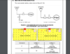
I made my own schematic which I have attached below, I have already done the circuit for the Accelerometer and Gyroscope. The PCB I have made is just a prototype hence I have added jumpers to test it out if everything is ok, but feel free to suggest something else, also for the whole circuit itself.


I am not very experienced with PCB designing, I would like some help from you, my requirements for this PCB would be-
1) GPS
2) Accelerometer and Gyroscope
3) a Li-Ion battery charging circuit
4)Bluetooth

Since I would be mass producing this, I also need help in making it as easily manufacturable as possible.

Thank you very much.
 

Attachments

  • Prototype_1.pdf
    57.9 KB · Views: 243
What's your budget? How much are you willing to pay for the help?
 
What's your budget? How much are you willing to pay for the help?
I actually would want some guidance as to wether I am doing it right, in the right way, that is why I have made a schematic but just wanted help and posted it here
 
If you're just prototyping then the 4 things you want on the board are probably better being sourced as modules from banggood or ebay. For a prototype, EasyEDA have the processor you state in the pdf and will assemble the boards for you. You will need to add any through hole components.

Why is there a minimum size for thew PCB? It's normally a maximum size.

Mike.
Thank you, my bad I meant maximum size. What should I type in the search bar for these sites to get the right part I am finding? Because when I search for gps modules it is only showing me the antenna, not the entire thing- (https://www.banggood.in/Beitian-Dua...html?cur_warehouse=CN&ID=6300460&rmmds=search)

Is this the part for example that I need or are there more to a gps module/system?
 
Try finding the components you need on Ebay as modules and design a board with your processor of choice using EasyEDA, you maybe happily surprised at the cost of 10 boards that have the processor already in place. If you need help then just ask here.

Mike.
 
Try finding the components you need on Ebay as modules and design a board with your processor of choice using EasyEDA, you maybe happily surprised at the cost of 10 boards that have the processor already in place. If you need help then just ask here.

Mike.
Sure, I am only confused about the GPS module, because I can only see antennas. Can you suggest me some boards?
 
I checked this one out- (https://www.amazon.com/Microcontrol...ld=1&keywords=ublox+gps&qid=1620905200&sr=8-4), but I would like to integrate the antenna into my PCB is that possible for do I have to settle down with an external antenna?

I checked the spark fun board, but it was too expensive, but if I was to use it can I use an antenna built into the PCB?
Sparfun sell a GPS receiver with the antenna built in but it's too expansive for you. So, use a cheaper board and an external antenna. I always work on the principle, it's a prototype so I just want to get it working. I'd buy a $40 module if it proves my design. Once you prove your design then you try to make it cheaper.

Mike.
 
Hello everyone, I have made a schematic for this project, I need your help with somethings. I am not sure how to program this device the hardware components, I am thinking of programming this via USB, I have seen the ESP32 PICO D4 Dev kit, it uses USB for programming so I am thinking of doing the same. I am trying to follow this schematic as close as possible- https://dl.espressif.com/dl/schematics/esp32-pico-kit-v4_schematic.pdf

I am not very sure of wether I have done the right things with my schematic, please do let me know if I've gone wrong somewhere. I will definitely explain if you have any questions.

The components I have chosen are-

1) ESP32 PICO D4 (Microcontroller) -https://www.mouser.com/datasheet/2/891/esp32_pico_d4_datasheet_en-1365829.pdf

2) XC6210B332MR (3.3v LDO) - https://www.torexsemi.com/file/xc6210/XC6210.pdf

3) MCP73831T-2ACI/OT (Li-Ion Charging IC) - https://www.mouser.com/datasheet/2/268/20001984g-846362.pdf

4) ICM-20948 (9 axis IMU) - https://product.tdk.com/system/file...l/imu/data_sheet/ds-000189-icm-20948-v1.3.pdf

5) 211964-0001 (Ceramic Antenna) - https://www.mouser.com/datasheet/2/276/2/2119640001_ANTENNAS-1912770.pdf

I also I need help with the antenna, I am not sure wether I have done it right, and chosen the right one. There might be some more help that I need with this, I am just doing this as a hobby, I have no professional experience in building electronics. Please do let me know if there are any changes that need to be made to this. Thank you for your help.
 

Attachments

  • v1.0.pdf
    48.8 KB · Views: 203
Last edited:
Sparfun sell a GPS receiver with the antenna built in but it's too expansive for you. So, use a cheaper board and an external antenna. I always work on the principle, it's a prototype so I just want to get it working. I'd buy a $40 module if it proves my design. Once you prove your design then you try to make it cheaper.

Mike.
ok, I was also thinking if I could straight up make a board and continue with it? I also seem to be stuck as to how do I use these GPS modules. I have also posted my schematic, it is without a GPS, I am thinking of adding it later. I chose the ublox M8 GPS module. It has an onboard antenna. I would like some help with using an ESP32 PICO D4.
 
Guys sorry you can draw your pcb layout on proteous and send the layout to any company for printing it! ? Or once you draw pcb layout you will be responsible your self for printing it?!!!
 
Guys sorry you can draw your pcb layout on proteous and send the layout to any company for printing it! ? Or once you draw pcb layout you will be responsible your self for printing it?!!!
I don't understand what you are trying to say here. I use EasyEDA to do both schematic and board layout. It's free and you can use any PCB manufacturer you like. I personally get the boards made (and populated) by JLCPCB.

Mike.
 
Guys sorry you can draw your pcb layout on proteous and send the layout to any company for printing it! ? Or once you draw pcb layout you will be responsible your self for printing it?!!!
I dont think so, you can use any pcb design software send the Gerber files and order the PCB online
 
I also would like to know, in the manufacturers description of this product, it says C1 and C2, but C1 (I am running it on 2.4GHz) is a 2.7pF capacitor and 0 ohms for C2. Does C1 and C2 mean components? And what can I do for the 0 ohm resistor? Shall I just connect it straight to the MCU?
 

Attachments

  • Screenshot 2021-06-27 at 3.27.47 PM.png
    Screenshot 2021-06-27 at 3.27.47 PM.png
    323.6 KB · Views: 222
C1 is a capacitor and C2 is just continuous track rather than a gap and capacitor.

Note that the track size, lengths between cap and antenna pad, spacing from that to the ground plane either side and ground plane cutouts on both sides are absolutely critical for it to work.

The drawings in the specification document are better; you need the dimensions as on page 8, but for 2.4GHz only you want to use the three connection arrangement as in the left diagram on page 9.

Note that item is a bare antenna for a WiFi or Bluetooth device - it cannot connect to an MCU, only a device with built-in 2.4 GHz RF system and stripline connection.
 
Status
Not open for further replies.

Latest threads

New Articles From Microcontroller Tips

Back
Top