Continue to Site

Welcome to our site!

Electro Tech is an online community (with over 170,000 members) who enjoy talking about and building electronic circuits, projects and gadgets. To participate you need to register. Registration is free. Click here to register now.

  • Welcome to our site! Electro Tech is an online community (with over 170,000 members) who enjoy talking about and building electronic circuits, projects and gadgets. To participate you need to register. Registration is free. Click here to register now.

PCB considerations with microcontrollers?

Status
Not open for further replies.
HarveyH42 said:
Figure sinse they are flashing, not constantly on, everything could handle a little abuse, and I'd get brighter output.

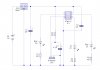
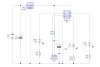
lots of projects drive leds directly from the pins, relying on the internal resistance of the switch(es) to limit current. it may not be a wise choice for a commercial product designed to sell in huge quantities, but for a homebrew project, it is something you may want to consider.
 
Success!!! The 4.7 uf cap across the IR module's power leads did the trick. Also had to point the IR module and IR LED away from each other slightly. And as a bonus, detects my hand at a little over 12 inches.
 
Attached is a better schematic of what I have on the working PCB. Let me know if you see anything I need to fix before doing a new PCB from it.
 

Attachments

  • Tiny13Police.jpg
    Tiny13Police.jpg
    62.1 KB · Views: 130
if I had to choose, I'd move C2 to the output side of the 78l05, as the input capacitor is optional, the output capacitor is not (according to the datasheet).

does the ir gizmo really need 4.7uf to decouple it?

how about a 0.1 uF cap for the cpu, just to make all us worry-warts happy ;)
 
Made the changes. Probably have to go with thinner traces to keep the board small...

One of the post suggested 4.7-47 uf on the IR module, tried it, fixed the problem. Maybe this was why I couldn't get it to work with pin change interupts...
 

Attachments

  • Tiny13Police2.jpg
    Tiny13Police2.jpg
    68.2 KB · Views: 140
Last schematic is perfect. I was gonna say, you to not need the input CAP as using a battery.. But JustDIY got that. And it was too small for real use anyway there.

And moving it where you did, you have the decoupling you need since you have a 38Khz signal on it.

But I think it will work without that cap all together ;)
 
I was gonna say, you to not need the input CAP as using a battery.. But JustDIY got that. And it was too small for real use anyway there.
He could also just put the pads on the PCB and not install it.
Maybe a diode in series with the B+ line from the battery in case someone accidentally brushes the contacts across a battery the wrong way.
 
the vreg's internal reverse polarity protection should protect from a 'brush', but an external diode would be cheap insurance

edit: just to add ... personally, I loath the 9v battery. they are expensive and impotent. how about running your kit off two, three or four AA size batteries, then you can do away with the regulator... since right now, your vreg is burning almost as much power as it is regulating (9v - 5v = 4v to burn), things get better as the voltage drops
 
Last edited:
justDIY:

That is how I do it.. 2 or 3 AA or AAA cells are great. No drop/lose.

EDIT: Taught years ago. If battery, no regulator.. I cannot name the one that yelled at me. You all know who you are!
 
Last edited:
Status
Not open for further replies.

Latest threads

New Articles From Microcontroller Tips

Back
Top