Continue to Site

Welcome to our site!

Electro Tech is an online community (with over 170,000 members) who enjoy talking about and building electronic circuits, projects and gadgets. To participate you need to register. Registration is free. Click here to register now.

  • Welcome to our site! Electro Tech is an online community (with over 170,000 members) who enjoy talking about and building electronic circuits, projects and gadgets. To participate you need to register. Registration is free. Click here to register now.

PCB considerations with microcontrollers?

Status
Not open for further replies.

HarveyH42

Banned
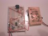
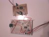
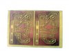
This past week I've made two PCBs for my Tiny13 project (IR Proximity alarm), and still can't get it working quite right. The first board was a sloppy rush job, small and thin traces, couldn't do much to re-working on it, so scrapped it. The second one, I took my time, made sure I had extra room if I needed to add or change anything. Made very sure everything was the same as the breadbord circuit. Only had to reverse one LED...

The problem is noise or crosstalk on the PCB. The IR emitter flashes a little over 38kHz, the reciever module is working right, but the Tiny13 is constantly triggered. The program and circuit works great on the breadboard, but on the PCB the LEDs never stop. Put a delay loop in the wait-for-input routine, so I know it's not malfunctioning. I can pull the chip off the PCB, plug it into the breadboard circuit, works fine.

I'd post the schematic, but its kind of a rough, minimal sketch likely to generate some unpleasant responses. I'm looking for a more general reason why something could work fine on a breadboard, but have signal problems on a PCB.
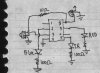
 
Something is definitly being done wrong when you change the circuit over to PCB, you should have no real problems with a circuit like that on a simple PCB, you may be getting odd reflections? You really need to send some pictures of the breadboard setup and then your PCB setup, and/or the schematic otherwise we're not gonna be able to help in the slightest.
 
How about posting the PCB?

Are you absolutely certain the connections are correct?

Are there any amplifiers with high source impedances been driven from high impedance sources?

There might be a chance that capacitive coupling is messing things up.

Don't worry about posting the schematic you'll probably get more help by posting a crap one than none at all.
 
Yea, better post it Harvey. 38Khz is not fast, PCB should be better. Also, Atmel makes a good chip. Decoupling is a thought like JustDIY said, but in simple circuits (single chip) I never used decoupling with the Atmels.
 
mramos1 said:
Yea, better post it Harvey. 38Khz is not fast, PCB should be better. Also, Atmel makes a good chip. Decoupling is a thought like JustDIY said, but in simple circuits (single chip) I never used decoupling with the Atmels.

Guess I'm old school. I always decouple. 0.1 or 0.01 are cheap and common, get an old TTL circuit board and they decouple every 74 series chip.
 
William At MyBlueRoom said:
Guess I'm old school. I always decouple. 0.1 or 0.01 are cheap and common, get an old TTL circuit board and they decouple every 74 series chip.

If you don't decouple, don't complain when circuits don't work!.

PIC's seem to work quite happily with no decoupling as well, but I wouldn't dream of building a circuit without them!.
 
I'd check the wiring to make sure all the connections are correct - beep-out each uC pin and double check the circuit.

The only other reason would be the parasitics that breadboards have - they tend to put arbitrary pF level capacitances between nodes. Normally this doesn't matter, but it'll play havoc with crystal oscillators and sensitive amplifiers.
 
Guessing from the replies that there isn't anything too critical I missed in putting this together, so it must be a mistake I'm missing on the PCB. Been through it many times, fixed several problems, replaced some components.
Attached is a scan of my schematic, it's just a rough sketch from the breadboard. Mostly I just needed to know which pins are connected to what.

The pictures... not my best photography, but might help.
 

Attachments

  • Tiny13IR.jpg
    Tiny13IR.jpg
    58.8 KB · Views: 205
  • Tiny13IR_BPCB.jpg
    Tiny13IR_BPCB.jpg
    52.7 KB · Views: 190
  • Tiny13IR_BPCB2.jpg
    Tiny13IR_BPCB2.jpg
    47.9 KB · Views: 193
  • Tiny13IR_PCB.jpg
    Tiny13IR_PCB.jpg
    52.4 KB · Views: 186
is that some sort of TO92 voltage regulator, 78L05 or similar?

have you tested to see that it's operating normally? it appears as though you have the output of the regulator bypassed, but what about the input?

also I wonder if it is overloaded ... depending on the supply voltage, three LEDs and a cpu might be too much for it?
 
The regulator is on the breadboard as well.. But I see a CAP not on the schematic that is on the breadbaord,. If worried about current, try 220ohms over the 100ohms maybe.

Your board looks nice. What did you make them with (cad software)?

Don't feel bad, I spent hours trying to get a POT and LED to work on a pic once (the ADC/pot worked fine, could not get the LED to flash). It happens (damned new PIC defaults).

EDIT: I would, check power and ground. Then mod code to blink the LEDs (see if it is stable). Then send IR RX data and put an IR detector on a scope and see if the signal is there. In other words, break it down in the code and test it. I tried to trace the runs, but without the placement diagram, I was lost after the pin 2 LED and resistor to a pin by a coulpe others pins :). Pin one is not connected, that was easy..

If it is in Eagle attach it and I will trace it out. Sometimes you can stare at it for a long time and not see it
and another will in minutes.. I find sometime I just leave it, go do something else and come back and I see what I did.. :)
 
Last edited:
justDIY said:
is that some sort of TO92 voltage regulator, 78L05 or similar?

have you tested to see that it's operating normally? it appears as though you have the output of the regulator bypassed, but what about the input?

also I wonder if it is overloaded ... depending on the supply voltage, three LEDs and a cpu might be too much for it?

Yes, it's 78L05, 100mA should be enough. The IR LED flashes at 38 kHz, the red and blue flash alternately. The supply is a basic 9 volt battery.

I did have to make some changes to the PCB. Had to cut a trace, it ran from the battery negetive to the output of the 78L05. Could blame the software I used, but should have caught it before I made the board. Also had to move a resistor running from the IR module and to the output of the regulator. Forgot the 1 uF cap on the PCB across the +/-, added it later just incase... Also the trace that is mostly the common ground, never made it to the battery negetive, so had to add a bridge.

The program is working, the LEDs flash as instructed. The IR LED is flashing at a little over 38 kHz, good square wave on the scope.
 
HarveyH42 said:
Guessing from the replies that there isn't anything too critical I missed in putting this together, so it must be a mistake I'm missing on the PCB. Been through it many times, fixed several problems, replaced some components.
Attached is a scan of my schematic, it's just a rough sketch from the breadboard. Mostly I just needed to know which pins are connected to what.

The pictures... not my best photography, but might help.
Hi Harvey.

please try check the connections of the part on pins 3 and 8 via 10 ohms , third limb eth.

i saw your last post now. Congrats then
 
Last edited:
Harvey, try Eagle for the cad part. It will keep a lot of weird things like that from happening.

I missed the IN and OUT short on the regulator, but some people (ok me) do that when I deceide I am going battery and do not need the regulator :). I can cut is with an exacto later if I need it..
 
Well, took some advice, and pulled the IR LED off the PCB, seemed to be only thing screwing up the works. Figured I could use the 555 circuit I made to test the IR module before I started this. Unfortunately, I'm using that breadboard for this project, forgot I ripped it up for this...

The weird thing I discovered... Kind of short on time, so figured I use the VCR remote and a spring clamp for a 38 kHz IR source. Pushed a button, the lights triggered from across the room. Runs through the flash cycle and then waits. Tried it a few times.

The only difference from the breadboard and PCB is where I put the resistor for the IR LED, didn't think it would make any difference, the load would be the same. The resistor could be 10 ohms instead of 100, the brown and black look kind of similar. Have to test it and see, has a free end now...

Should leave this for tomorrow, getting kind of late for me, but think I'm getting close.

Oh, should mention, using the same IR LED on PCB and breadboard, has a plastic shield, and the reciever set slightly behind. Also, tried seperating with a divider. Doubtful it's optically triggering the reciever.
 
HarveyH42 said:
Guessing from the replies that there isn't anything too critical I missed in putting this together, so it must be a mistake I'm missing on the PCB. Been through it many times, fixed several problems, replaced some components.
Attached is a scan of my schematic, it's just a rough sketch from the breadboard. Mostly I just needed to know which pins are connected to what.

The pictures... not my best photography, but might help.
First off read the data sheets, it's 100ohms for the IR (not 10) and you do need a small cap 4.7uf to 47uf for it to work. (see my firefly schematic for details)
Second add a 0.1uf across the CPUs power pins as close as you can, and check the LM78L05 data sheet and you'll see more caps there too. They are there for a reason.
 
William At MyBlueRoom said:
First off read the data sheets, it's 100ohms for the IR (not 10) and you do need a small cap 4.7uf to 47uf for it to work. (see my firefly schematic for details)
Second add a 0.1uf across the CPUs power pins as close as you can, and check the LM78L05 data sheet and you'll see more caps there too. They are there for a reason.

Used 100 ohms on everything on the PCB (mis-read the bands dark brown/black).

Data sheets... Don't have a part number for the IR module, so guessing and a little experimentation got it going. Will add a cap tomorrow (up a little late as it is...).

Caps for the MCU and regulator... It's battery power, shouldn't be critical, but will check that data sheets and see why.

The breadboarded circuit works fine, about 6 inch range. PCB version not so good, but getting better. The cap across the IR module's power pins sounds like it might help, being there might be some fluctuation when the IRled fires, and this would be the same 38 kHz it needs to detect.
 
Hi,
Try a small reflector for thr the IR LED sothat it will focus in one direction-this is what happens when you use tv/vcr/dvd/ remote with 38KHz. it has a built in moulded reflector.
perhpas you coud moumt 78L05 by manipulating the pins.(unless it is a college project and there should not be a mistake---

the IR receiver could be SFH506 (TSOP1736) as i could see the shape and pin configuration.
datasheet at
https://www.alldatasheet.com/datasheet-pdf/pdf/26588/VISAY/TSOP1736.html
the series resistance could go upto 330ohms with 1uF cap across the device.
the cap may perhaps help in cleaning up post resistor voltage and help boost the range

all the best
 
Thanks for the part number, will get the data sheet in a little bit. The IR LED has a plastic shield around it (one reason I chose it). I've got several old remote, maybe tear one open and see about a reflector.
The 78L05 is already there, its a TO-92. Haven't been in college for about 20 years, this board is getting pretty tired (traces coming loose). I'll have to make a new one after I get the bugs out anyway.

Getting a lot of good advice, and feel it's getting close. Still don't know why it would work on the breadboard, same MCU chip, but not on the PCB. There is one thing that maybe a problem, the Tiny13 can provide 20mA directly, but the 100 ohm resistors I chose to use are a little low for the LEDs I'm using. Figure sinse they are flashing, not constantly on, everything could handle a little abuse, and I'd get brighter output.
 
20ma's yeah, but not at full supply voltage. With a 5 volt supply an I/O line will source 20ma's at 4.2 volts according to the PDF, so with that resistor you may be sourcing less voltage than you think to the LED.
 
Status
Not open for further replies.

Latest threads

New Articles From Microcontroller Tips

Back
Top