Continue to Site

Welcome to our site!

Electro Tech is an online community (with over 170,000 members) who enjoy talking about and building electronic circuits, projects and gadgets. To participate you need to register. Registration is free. Click here to register now.

  • Welcome to our site! Electro Tech is an online community (with over 170,000 members) who enjoy talking about and building electronic circuits, projects and gadgets. To participate you need to register. Registration is free. Click here to register now.

PC not correctly emulating the radio module. Is my circuit bad?

Status
Not open for further replies.

mik3ca

Member
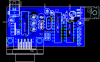
I made the following circuits. The first one is an application run on the microcontroller and it allows me to see data on a PC terminal via a serial port. Yes, I'm using a software uart. There's the circuit:

circuit.png

The HM-TRP connection point means a connection to the HM-TRP radio module. Now the next circut...

circuit2.png

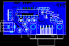
This next circuit is supposed to function as a simple PC to microcontroller serial port data provider.

Because I don't want to mess up the radio modules, what I did to try to simulate a module is connect pin 4 of circuit 2's SV1's pins to pin 2 of circuit 1's HM-trp's connection pins and I also connected Pin 2 of circuit 2's SV1's pins to pin 4 of circuit 1's HM-trp's connection pins. That way I can hook up circuit 2 to the PC and use that PC as if it was the radio module.

Even though neither circuit blows up, I'm not getting correct data, yet I set every single baud rate n the circuits to 57600bps. (57600 in the micro software UART, 57600 in the micro hardware UART and 57600 in both PC's attached to the circuit.), and both machines are running slackware linux, except one machine is using one release earlier, but I don't think that matters does it?

On the PC connected to circuit 2, its reporting that it receives a bunch of FFh, and the micro is telling me its receiving a bunch of 00h.

What's strange is that I tested circuit 2 by itself with the PC by hooking up the transmit and receive pins (pin 4 and pin 2) together, as if I was making an overkilled serial loopback interface, and it did function as such with absolutely no error.

I also tested the transmitting functionality of the first circuit and it seems to work OK (I only had an LED to test with).

The only thing that might be the case is that I converted 5V to 3V at the HM-TRP connection point so I don't blow up the actual radio module when I'm ready to use it (Its max voltage is 3.9 I think).

Is there something I can add and/or remove to these circuits to make both computers be able to communicate with each other through these circuits?

Below is an image of the jumper connectors I'm using to connect the two circuits together (I rip one connector off from the whole group of connectors), and both circuits have good power.

Jumper_Leads_F_F.jpg


I have also measured pins 2 and 6 of the max232 and they come out as +9 and -9V so I could be guessing it might be a matter of moving certain resistors and/or adding more?
 
I take it you don't have a scope to actually scope what's appearing directly on the MCU pins and at the output of the whole circuit?

What's strange is that I tested circuit 2 by itself with the PC by hooking up the transmit and receive pins (pin 4 and pin 2) together, as if I was making an overkilled serial loopback interface, and it did function as such with absolutely no error.
That's not very strange at all since each unit is transmitting and receiving in a way that is self-consistent.

On the PC connected to circuit 2, its reporting that it receives a bunch of FFh, and the micro is telling me its receiving a bunch of 00h.

If your bytes are always being interpreted as perfectly inverted, then there's probably an unknown setting somewhere hidden in the MCU to swap signal , idle states, or logic levels, or polarity (intended to correct reversed wires in balanced signals signals in sofware.)
 
Last edited:
I take it you don't have a scope to actually scope what's appearing directly on the MCU pins and at the output of the whole circuit?
If I'm not mistaken, such scopes cost a ton of money. A PC is closest thing I got to analyzing the data, although I could chain up a bunch of 74HC164's and 74HC165's together with a fixed clock but even then I gotta freeze the data and that takes more circuit board. I used the first circuit configuration before to run the radio module only as a data device and it worked then but I want to test the pin output with a device (such as a PC) because this first circuit will eventually allow me to program the radio modules and I don't want to accidentally give it the wrong baud rate and render the radio module useless.

If worst comes to worst, then I guess I'll have to hack the IC socket so that a wire as well as a pin from the micro can both fit in the same socket so I can analyze the data from there while the circuit is running and if that works, then I can't understand why it won't work at the 3V level.

If your bytes are always being interpreted as perfectly inverted, then there's probably an unknown setting somewhere hidden in the MCU to swap signal , idle states, or logic levels, or polarity (intended to correct reversed wires in balanced signals signals in sofware.)

I could look at the manual more but I don't know if I can find clues there. For reference, the micro I am using is AT89C4051-24PU.
 
I'm curious... Are my parts preventing me from running everything at 56kbps? Because when I ran tests on circuit 2, I didn't get the same number of bytes as what I sent. I sent 8 different bytes and received on the other pc only 3 or 4 bytes (all FFh)
 
Well, I only ask about scoping because you seem to not have ruled out a hardware and if it is you may never find it unless you scope directly at both ends of the circuit. You can get something sufficient for that task for $100 or $200.

You said you are running a software UART right? In other words, you're bit banging rather than using a peripheral? Because if you're using bit-banging code then you will need to look into that code to see if there is a reversal setting somewhere. The MCU datasheet would only help you if you were using a hardware UART module.

I assume the software UART code is already known to work since seem to not have any suspicions about it.

Also, keep in mind that if examining the received data on the PC from the MCU, it might not be obvious if the data polarity is reversed. I had this happen to me 3 weeks ago and it was only obvious what was going on with bytes like 0x00 or 0xFF. Anything else would look like some weird kind of partial reversal, sign extension, twos compliment conversion nonsense.

I'm curious... Are my parts preventing me from running everything at 56kbps? Because when I ran tests on circuit 2, I didn't get the same number of bytes as what I sent. I sent 8 different bytes and received on the other pc only 3 or 4 bytes (all FFh)
But if this is really happening, then it doesn't sound like a polarity/logic reversal. I don't know what to tell you here but this is kind of the reason you might need a scope, or something if it is really is a hardware issue (if it's not the UART code). Are you SURE your baud rate and wait states are set correctly on both ends?

Have you tried wiring circuit #1 so the MCU sends messages to itself? Then write some code to send a bunch of different bytes and light the LED if they match or don't match. If they don't then you know that's a hardware issue (assuming the soft UART is okay).
 
Last edited:
You said you are running a software UART right? In other words, you're bit banging rather than using a peripheral?
That's to the primary PC. That part is working because the correct data is being printed to the screen and being accepted from the same computer. The hardware UART is what will be connected to the radio module once things work, but for now, I'm trying to make the second computer act as the radio module using the second circuit I showed.

The MCU datasheet would only help you if you were using a hardware UART module.
It didn't help. It talked about power down and idle modes yet I never executed any code that would cause it to enter either mode.

Also, keep in mind that if examining the received data on the PC from the MCU, it might not be obvious if the data polarity is reversed.
I think this is where I need to direct my issue to. polarity. Is there a circuit somewhere I can use for that I can put in the middle of my serial lines so that the polarity can be fixed?

Also, because the radio modules only work for half-duplex, trying to make them full duplex is not a good idea for me at this time. But given my circuit, maybe I need some polarity conversion because the connections to the radio module pins are all 3.3V max and the output to the pin is 3.3V or 0V. Yes I used a 74HCT04 inverter with a voltage regulator to convert 5V signals into 3.3V and vice-versa.

I want to try the polarity correction idea first with a simple circuit from commonly available parts
 
Oh, so in the end it should be:

(Radio) -> CCT#1

BUt for testing you have replaced the radio so it is:

(PC -> CCT#2) -> CCT#1

This port is half duplex and using a hard UART on the MCU?

And CCT#1 allows another PC to snoop the data on the line. The MCU is using a soft UART for this snooping port but it is working fine.

And you are saying that when the PC emulating the radio sends bytes to the MCU, a lot of them are getting missed and of the few that do get through, the MCU is reporting that they are the opposite of what they should be (according to the snooping PC).

I'm not very familiar with the way AT89C4051-24PU documentation is arranged. Can you link the the manual you are looking at? I keep running into the 19 page datasheet that doesn't tell anything about the UART peripheral.
 
Last edited:
And you are saying that when the PC emulating the radio sends bytes to the MCU, a lot of them are getting missed and of the few that do get through, the MCU is reporting that they are the opposite of what they should be (according to the snooping PC).

Yes, but the bytes the radio emulated PC receives is always FFh but the PC knows when new data is being sent and it also received fewer bytes than the 8 that circuit 1 sends through the hardware UART. Also, recieving is also incorrect as well. It seems as if nothing is received.

So it makes me wonder if the max232 chip on circuit 2 is creating a problem.

Oh, wait. I think I understand your circuit better now (sleepy). in CCT#1, the MAX232 is just for the snooping PC. The MCU just talks to the "radio" directly through two inverters used to change the voltage levels.

[second part of post redacted since I realized things while looking at the circuit more that made my questions or suggestions nonsensical]
 
Last edited:
I intentionally hooked two inverters together as shown in my circuit to produce the original non-inverting output. If I only used one inverter, then the output would be inverted. I'm not quite understanding what you mean by IC1F and ICVF and I'm not sure if 10K is too big but I don't want to go too low or I'll be sucking up power like crazy (ohms law). although I did find a similar design with the transistors in which the pullups are 1K.
 
Are you powering all the inverters off 3.3V? it's possible that the last inverter on the RADIN path is unable to properly trigger a logic HI in your 5V MCU. That would be consistent with the difference between the MCU and snoop PC readings.

You can test in two ways:

1. Power your inverters off 5V.

2. Your CCT#2 is driving using 5V right now so disconnect the inverters in RADIN and bypass them with a piece of wire.

See if that changes things. If it does, then that's your problem.
 
Last edited:
I can already conclude that part works ok because I did that setup in an earlier circuit and was able to transmit and receive data with the radio module in place.

Maybe I do need to change the resistors in circuit 2 because transistors have capacitance and factoring that in with the resistors might be the main issue. I read somewhere that using a bad combination of transistors and resistors means slower processing speed (propogation delay)

Oh, so it actually did work with the radio module there? Yeah, if that was the case then the inverters are able to trigger things properly and the problem must be in CCT#2 somewhere. In that case back to my first suggestion which I redacted earlier about trying <10K resistors in CCT#2.
 
Actually, I took a look at the MAX232 datasheet. You don't even need those transistors there as a voltage translator. You can drive the MAX232 TIN pin directly from a 3.3V device. At 5V power, the MAX232 accepts anything above 2V as a logic high while 3.3V devices typically output 2.31V minimum for logic high.

You also don't need IC1F or IC1E since the radio module driving 3.3V to the 5V MCU won't do any harm to the MCU, and the inverters are being powered off 3.3V anyways so it's not like they are boosting the voltage of the 3.3V radio to the 5V MCU.
 
Last edited:
Before I rip apart my circuit, I read on texas instruments website about keeping some leads on the max232 to the capacitors short. I made my leads fat so that theres a lower resistance path. Is that setup I did in the PCB ok or does that prevent me from using 56K speed?

P.S. I attached my PCBs.
 

Attachments

  • circuit1.png
    circuit1.png
    18.3 KB · Views: 104
  • circuit2.png
    circuit2.png
    10.6 KB · Views: 103
Also, I read that distance in a serial cable can affect speed which might explain why I get the wrong number of characters. The cables I use are 3 feet made from techcraft that I hook between the modules and the PCs. I'm also wondering if the jumper wire connection I'm using as explained is also bad. In my tests, the computers were placed about 2 meters apart.
 
You should be fine. I run a 3 Mbps UART on a solderless breadboard at work. 57600 baud is really REALLY slow, so slow you can get away with a lot of things. Cable and layout quality or length shouldn't be an issue. Decoupling and charge pump capacitors in general should be kept short to improve noise and it's just good practice for any board of IC. You can solderless breadboard 8MHz quite easily so layout limiting speed is not your problem here.

Don't "tear your circuit up". Just disconnect the transistor level translator input or output in CCT#2 and bypass it with a jumper wire.
 
Last edited:
ok, now Im getting somewhat better progress (at least I'm not just getting a bunch of null and FFh characters). I replaced the two-transistor circuit with just a 1K resistor and a ferrite bead in series for protection (almost a short). I'm going to change the batteries later or possibly use a second adapter. and see if that helps even though 4 AA batteries that were used to power circuit 2 were just measured at 5V. If that still fails then I might lower the resistor value but I do not want to create any unforseen issues with my circuit (sorry I have bad luck lately)
 
You can also test if the inverters are causing any unforeseen or intermittent issues by bypassing all the inverters while you're using the PC-emulation.

When interfacing IC of different voltages, always look in the datasheet for their input and output logic high and logic low levels to know what you can get away with.
 
Status
Not open for further replies.

Latest threads

New Articles From Microcontroller Tips

Back
Top