Continue to Site

Welcome to our site!

Electro Tech is an online community (with over 170,000 members) who enjoy talking about and building electronic circuits, projects and gadgets. To participate you need to register. Registration is free. Click here to register now.

  • Welcome to our site! Electro Tech is an online community (with over 170,000 members) who enjoy talking about and building electronic circuits, projects and gadgets. To participate you need to register. Registration is free. Click here to register now.

PC monitor does not turn on

Status
Not open for further replies.

JMaia

Member
So the other day my PC Monitor just turns off by itself. Hoping that it would be maybe just a broken fuse, I opened the monitor, but I was hoping to see a cartridge type fuse, but there was none of that that I could see on the PCB:

2021-02-09 14.11.24.jpg


Could anyone give a hint on how to troubleshoot the problem, since I clearly don't know what I am doing?
 
There's a note about a fuse in the lower left corner of the board. Can you get a clear picture of this area?
 
The brownish item lower left, close to the blue capacitor seems to be a 4A fuse of some sort. Some are also thermal fuses. Look up the part number if possible, or just check continuity across it. Check the NTC therminstor beside it as well
As a note, the capacitor to the left of the two large orangeish resistors seems to be bulging. Check all caps for bulges. That is a common problem with a lot of monitor power supplies, bad caps.
EDIT: There is also a fuse on the upper right of the picture, similar rectangular one which I assume is output.
 
4A A/S fuse lower left (brown component soldered in) - worth checking, but I'm dubious that will be the problem.

There are two diodes, D901 and D9xx, above each other - these could well be in parallel - a flawed circuit configuration which causes them to fail (one or both go S/C), it might be worth sticking a meter on ohms across those?.
 
monitor eletronics numbered.jpg


So I googled how to test fuses (i have a cheap mulltimeter). I marked the things I tested with numbers on the photo above.

1 - this is what I think is called DC or AC jack, it's working
2 - cant get it read any resistence, seems to not be working?
3 - works
4 - same thing as number 2
5 - same thing as number 2
6 - works

Isn't a bit strange that none of the blue caps work? Maybe I'm doing something wrong? After googling im using the method:

Measure the Fuse.

Important! Place the fuse on a non-conducting surface such as wood, laminate or plastic. Touch the metal caps at each end of the fuse with the metal tips of the testing leads. There is no polarity so you can use any lead for either fuse cap. Ensure to make good contact by touching a clean metal surface on each cap. Whilst the leads are firmly connected to the fuse, look at the reading displayed on the multimeter.

Note: If you wish to test a fuse still located in a circuit. Please ensure that you have turned off power and disconnected the power source to avoid possibility of electric shock.
 
Item to the right of #3 is a thermistor, basically a low resistance device that limits surge current on startup. Check that as well. The blue items are capacitors, you cannot test those with an ohm meter ain resistance mode.
BD901, the bridge rectifier would be the next item to check. You can use "diode test mode" to check between each pair of legs. You should get conduction in one direction, a high reading (open) with the leads reversed. (one AC lead to each of + and -, then other AC leg to + and - points)
 
If everything checks out, turn on the power and verify you have a high DC voltage across the capacitor C907 to the right of the diode bridge (the big thing). Be very CAREFUL, it may have a high enough voltage to kill you. If you are getting a good DC voltage there (around 150-175VDC with 120V AC input), then everything up to that point is likely good.
Next suspect item would be Q901, the switching transistor (or MOSFET). That you may have a hard time testing without removing it, and looking up the part number to determine "how" to test it.
 
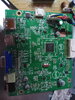
Ok so I updated the picture below:

monitor eletronics numbered.jpg


1 - this is what I think is called DC or AC jack, it's working
2 - Dont know how to test
3 - works
4 - same thing as number 2
5 - same thing as number 2
6 - works
7 - works
8 - BD901 not sure I'm testing correctly, please read below
9 - don't know how to test


Number 8 (BD901) Has 4 legs, one is -, other is +, and other 2 dont say nothing. I google how to use diod test mode on multimeter, I think my multimeter has that mode, in the picture is my multimeter with what I think is diod test mode selected:

2021-02-12 14.00.15.jpg


I google how to test using diod mode. When I use red lead on +, and the black lead on the unnamed legs, I get no reading, only 1 appear on screen.

If I use Black on + and red on the unnamed ones, I get a reading of 683 and another of 702

If I use black on - and red on unnameds, I get no readings.
If Red on -, I get readings of 686 and 691 on unnameds
I black on - and red on unnameds, no readings

Is the BD901 working? Am I testing it correctly?

Can you tell me how to test nr 9 correctly and safely? Would be cool if I accidenttaly don't kill myself since I have stuff to do this weekend.

Many thanks for the help and best regards
 
Your diode readings appear to be correct. Look up bridge rectifier to see how the diodes are arranged. The diode test is correct when measuring across a single diode. With leads the other way around, you get no reading (high resistance). With leads the right way around, you get the "forward voltage drop" of a working diode, which is usually around 0.7 volts (reading of 700)
You cannot just test the large capacitor (#9) with that meter except to measure the DC voltage when the unit is turned on. Unplug the power. Start with the 1000V DC setting, and clip the probes onto each leg of that capacitor. Only then turn on the device (plug it in). If you get that 160-175V DC with 120V household wall power, then everything between 1 and 9 is working ok. If using 240V household power, your DC voltage will be around double that - 320-340V DC. Remember that the voltage on that capacitor can be lethal if you touch it. After testing, unplug the unit and let it stand for a few minutes before touching anything else inside. You can re-measure capacitor voltage at that point to make sure it is close to zero, or a few volts only.
I did what you said, reading is about 320v (it's correct I'm from Portugal and voltage is 240v). When I unplug power reading is about 004.
 
That means the input side of the power is ok. The next suspect is the switching transistor, #10. Try to get the part number that is printed on it. After that, the diodes D901 and the one next to it should be tested, along with D906. D906 is probaby a 3 legged device, the center is usually a "common".
After that, the capacitor to the left of R922 looks like it may be bulging at the top. If so, it may be bad and affecting the feedback circuit. Any capacitor that is bulging at the top should be replaced. Check C918 as well, make sure the top is not bulging.
However, it all falls on #10 right now, that device may have failed, causing no output to the transformer feeding D901 and its companion diode.
 
Are there any device behind the heatsink of #10? That may be relevent in how #10 runs. Testing #10 is not easy, it may have to be removed and tested with a transistor tester, depending on what kind of device it is.
 
k6A65D is written on 10, the black thing with 3 legs, it's screwed to a grey thing that seems like a heatsink. Here is another picture with that shows more area around #10:

2021-02-13 15.41.20.jpg


BTW, there is another PCB that has the display connections, I iniattially didn't post a pic of it because it's a power problem, but that may have been a mistake of my part:

2021-02-13-15-48-26-jpg.129710


And another update to the numbered components:

monitor eletronics numbered.jpg


1 - this is what I think is called DC or AC jack, it's working
2 - Dont know how to test
3 - works
4 - same thing as number 2
5 - same thing as number 2
6 - works
7 - works
8 - works
9 - works
10 - dont know how to test
11 - not sure, see below
12 - same as 11
13 - same as 11
14 - this capacitor seems to be ok, don't think it's bulging, see clearer picture below
15 - same thing as 14

2021-02-13 16.10.44.jpg


11 and 12, i tried to test them using diod mode. I always get a reading a reading of 001 even if I reverse the leads

13 indeed has 3 legs. Using diod mode the "outside" legs always gives me a reading of 001 too, even with reverse leads. When I try to measure with the "center" leg, I never get a reading.
 

Attachments

  • 2021-02-13 15.48.26.jpg
    2021-02-13 15.48.26.jpg
    2.8 MB · Views: 539
Are you sure your meter is still in diode mode? #11 and 12 should show different readings when you reverse the leads. However, it is possible they have some transformer winding across them, producing a near-short when testing. Without a picture of the under-side in that area, hard to tell.
14 and 15 look ok.
At the output connector, there is a GND and a 5V labelling for the black and red wires. Can you measure any voltage there across those two color wires? There is an ON/OFF signal wire (green) as well, if whatever drives that is faulty, it is possible the power supply may not turn on. See if there is any voltage on the green wire relative to the black wires. All these voltages should be DC voltages, and all in the +5V to +12V range probably.
 
11 and 12, i tried to test them using diod mode. I always get a reading a reading of 001 even if I reverse the leads

As I said back in post #4 - those two rectifiers appear to be in parallel which WILL cause them to go S/C, it's a common design flaw on cheap equipment.

As an ex-TV engineer, the picture you posted was an instant 'red flag', and would have been the first thing I checked.

Disconnect one end of each diode, and check them out of circuit - they should read one way, and not the other - this is standard procedure, after they read S/C in circuit. Generally, you find one of them is short, and you should replace them BOTH with identical diodes, from the same packet (or even better, add a low value resistor in series with each as well).
 
Are you sure your meter is still in diode mode? #11 and 12 should show different readings when you reverse the leads. However, it is possible they have some transformer winding across them, producing a near-short when testing. Without a picture of the under-side in that area, hard to tell.

yes I'm sure I' using diod mode. Here's a picture of the area of diodes 11 and 12 from the under-side, I draw a red circle around the legs:

diods 11 and 12 under-side.jpg


I also tested them from the under-side BTW. Always a read of 001 even with reversed leads.

Disconnect one end of each diode, and check them out of circuit - they should read one way, and not the other - this is standard procedure, after they read S/C in circuit. Generally, you find one of them is short, and you should replace them BOTH with identical diodes, from the same packet (or even better, add a low value resistor in series with each as well).
I'll have to google on how to desolder components from the board, since I never try to do it. Any tips or link to a tutorial to someone who does not know what he's doing?
 
Did you check the voltages at the output connector first, before de-soldering anything?
Check the red to black and the green to black voltages first.
It could be the other controller board is not sending a "ON" signal via the green wire to the power supply, whatever that may be.
There are a lot of components on the underside, hard to diagnose with all those parts without a schematic now...
D901 and 902 seem to be tied together at one end, and the other end is probably the transformer. They should still show some junction voltage one way or the other with the leads. But, with all the other components, some of those may be messing up the readings. It is not so likely that those would be blown, at least not both at the same time. However, Nigel is correct, only way to properly test them is to lift one leg of each and check the diode junction.
 
Did you check the voltages at the output connector first, before de-soldering anything?
Check the red to black and the green to black voltages first.
It could be the other controller board is not sending a "ON" signal via the green wire to the power supply, whatever that may be.
There are a lot of components on the underside, hard to diagnose with all those parts without a schematic now...
I haven't desoldered anything yet.
Do I need to have power on the monitor to test those voltages? I'm sticking the leads to the pins but am not getting any reading in DCV 20 mode on the multimeter. I can only test on the underside BTW, heres a clearer picture:

2021-02-13 19.33.55.jpg


The monitor is a AOC G2260VWQ6, unfortunately I could not find any schematic, only the user manual: https://aoc-pim.s3.amazonaws.com/Pu...s/Manuals/G2260VWQ6/G2260VWQ6_English_1_0.pdf
 
I'll have to google on how to desolder components from the board, since I never try to do it. Any tips or link to a tutorial to someone who does not know what he's doing?

Heat up the pin underneath with the soldering iron, and pull that wire out from the top with pliers - with such big wires and the components nicely spaced off the board it's VERY easy to do.
 
Status
Not open for further replies.

Latest threads

New Articles From Microcontroller Tips

Back
Top