Continue to Site

Welcome to our site!

Electro Tech is an online community (with over 170,000 members) who enjoy talking about and building electronic circuits, projects and gadgets. To participate you need to register. Registration is free. Click here to register now.

  • Welcome to our site! Electro Tech is an online community (with over 170,000 members) who enjoy talking about and building electronic circuits, projects and gadgets. To participate you need to register. Registration is free. Click here to register now.

Passive Variable Bandpass Filter for White Noise

Status
Not open for further replies.

pnielsen

Member
I would like to build, from passive components, a single stage variable bandpass filter for a white noise source that operates across a range of about 100Hz to 10KHz. I realize the Q will be extremely low, but this is just a starting point that I will add to.

Can someone please advise regarding a suitable circuit configuration, and how to determine RC values for a mid point of about 5KHz? Being variable, the circuit would need to incorporate a potentiometer.

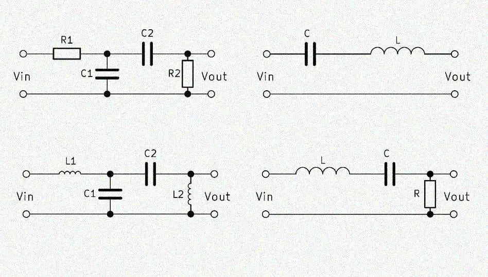
The diagram from the web, attached below, is included for comment.

variable_bandpass_filter.jpg
 
I don't know a simple totally passive bandpass...

Can you add a transistor? If so, you can base it around a simple twin-t notch filter in the amp feedback.
That's one type of circuit used in guitar "Wah" pedals, to create a tuneable bandpass. Still not many components, but far more effective than a pure passive circuit.

eg. See the firsty schematic on this page:
 
LC can certainly do BPF, with high Q, many variants. Problem is at these freqs component sizes/values
become a tad unwieldly versus doing it active. Especially as RC only -

**broken link removed**


Do you care about topology sensitivities or loading issues ?


Regards, Dana.
 
I would prefer passive. Just something that I can demo to myself how it is working, audio tone changes, etc.

No other criteria. But a specific example of how to calculate component values for the circuit in my OP would help get me started. For example 5KHz mid-range falling off to about 100Hz and 10KHz either side at perhaps 10% amplitude.

Is that do-able or do need to down-grade my expectation? Realistically, what should that be for single order? So far, the circuit I built is not producing a very noticeable change.
 
Why do you say you want a slope that reduces a level to 10% when 10% sounds like only half as loud because the sensitivity of our hearing is logarithmic.
An ordinary audio tone control is usually passive and cuts and boosts at 6dB (half or double the voltage) per octave. It is full output at 1kHz or 1.5kHz and when at maximum cut the low frequencies and high frequencies are reduced to 5% but can still be heard.

Your peak is at 5kHz but you want 10kHz to be at 10%? Not with passive, 10kHz will be at 50% and sound almost at the same level as the 5kHz that is twice the voltage.
 
Filter design tool to work with -


**broken link removed**


Regards, Dana.
 
OK. Log curve. That explains why I was not hearing much difference.

The calculator kindly suggested by danadak is for a two resistor, two cap design. I would need a dual gang pot to make that adjustable.

What is my best option in terms of component values for getting maximum variation with a single resistor (pot) and cap in the diagram I originally posted? As I understand, it is effectively a divider between two stages, one low and one high.

What variable frequency range in Hz could be expected from the values as shown (1K pot, 1uf, 47uF)? Since there appears to be no calculator for that configuration, this would give me a benchmark to work from.

Thank you for the helpful advice so far.
 
A lowpass filter made with one series resistor feeding a capacitor to ground and a highpass filter made with a series capacitor feeding a resistor to ground has the two filters affecting each other. If they are separated with a buffer amplifier then the slopes are gradual because the circuit is very simple.
 
What is my best option in terms of component values for getting maximum variation with a single resistor (pot) and cap in the diagram I originally posted?

Even the 'best' option would be useless, a first order filter if really very ineffective. If you want a working bandpass filter, then build a proper one from the start.
 
Here is a plot using ganged pot, one using 1 ohm each pot, then 1K each pot.

Your 1 pot topology did not yield a BPF.

1624184743897.png


Regards, Dana.
 
Last edited:
Here is a simulation of a very simple 1st-order bandpass filter.
In order to reduce 100Hz and 10kHz then it centers at about 1kHz.
1kHz is reduced quite a lot but 100Hz and 10kHz are not reduced much more.
A dual 47k to 100k pot is needed to make its frequency adjustable.
 

Attachments

  • simple bandpass filter.png
    simple bandpass filter.png
    27.8 KB · Views: 292
Just to clarify in my mind, is it true the single pot variable filter in my OP does not produce a significant effect? Here is the source website. https://www.jayrope.com/sweef

The point of the exercise for me was to learn about variable filters using the simplest possible circuit. If I need a gang, then I will proceed on the basis of the plots provided above. Now I know better what to expect.

Having said that, there does seem to be a difference in performance between the two circuits, 30dB vs 11dB. Can someone please explain, in terms of part selection, why this is occurring?
 
The Jayrope circuit is not a bandpass filter and it makes no sense. With the pot turned to the left side the 47uF capacitor shorts the signal to ground. With the pot set to the right side the circuit is a lowpass filter.

A single RC filter reduces frequencies at only 6dB per octave (doubling or halving the frequency) which is 20dB per 10 times or 1/10th the frequency.
The extremely simple circuit I simulated has no active parts to sharpen the peak and no buffer to isolate the lowpass from the highpass so they affect each other causing the 11dB loss at the peak level.
A single RC filter attenuates at -6dB (half the voltage) per octave (double or half the frequency) which is -20dB for 10 times or 1/10th the frequency.
 
The Jayrope guy says this much:
“Sweef in the displayed form is an experiment, that isn’t supposed to work, but actually does, sometimes ;)

And towards the end:
“I am not a tech expert, i work by ear.”

In other words, the circuit may or may not work, and when it does or doesn’t, he does not know the reason.

I can give a hint: the problem with totally passive filters, as a fact any passive filter topology, is that its response is wholly dependent on both the source and load impedance.
That is the single most important reason to use input and output buffers. Even a simple NPN source follower will improve things tremendously.
 
Thank you for the additional comments. I am still wondering why the two plots above differ to such a degree. If I read correctly, about 25dB in danadak's version vs 11dB in audioguru's (100Hz -10KHz). Since the topology is the same, can anyone please explain the reason for this, as it relates to component selection?
 
Short answer is different impedances used in the two simulation.

Regards, Dana.
 
Here is the difference between my filter and Danadak's filter. When I use the same ratio of capacitor values as in his then mine is the same as his:
 

Attachments

  • another simple bandpass filter.png
    another simple bandpass filter.png
    26 KB · Views: 269
Thank you again. I see that the frequency scale in your second plot is now extended to 100MHz, and the curve between 100Hz and 10KHz is no longer symmetrical. It is acting more like a low pass over that range.

From this, if I understand correctly, your first plot already had optimal values for my preferred bandpass function, and the 11dB variation is probably the best achievable for this topology.

However, I may try reducing the R values for lower impedance as danadak mentioned. Looking forward to a enjoyable weekend at the bench.
 
Last edited:
The very simple first-order bandpass filter has very poor performance. With its peak at 1kHz then its output at frequencies 100Hz and 10kHz are reduced only a little. There is still plenty of output below 100Hz and above 10kHz.
 
Its possible to get G out of purely passive RC networks, with some freq
response characteristics. G limited though.


Regards, Dana.
 
Status
Not open for further replies.

Latest threads

New Articles From Microcontroller Tips

Back
Top