Continue to Site

Welcome to our site!

Electro Tech is an online community (with over 170,000 members) who enjoy talking about and building electronic circuits, projects and gadgets. To participate you need to register. Registration is free. Click here to register now.

  • Welcome to our site! Electro Tech is an online community (with over 170,000 members) who enjoy talking about and building electronic circuits, projects and gadgets. To participate you need to register. Registration is free. Click here to register now.

Parallel port to keyboard circuit

Status
Not open for further replies.
Hello,

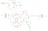
I am desinging a circuit that interfaces a ps/2 keyboard to the pc's parallel port. please view attachment to view circuit. Please note R9 and R14 are 470ohms. however the chip gets very hot and i dont know why. i dont even have the keyboard installed yet. is it a silly mistake or will i have to live with a hot ic.**broken link removed**.
 
Last edited:
the chip gets very hot
Which chip? There appears to be two.

Is the polarity correct? Your DC jack is wired for center-negative. This is unusual.

R1 needs to be a lower value, probably 120 ohms. Change R2 accordingly. The LM317 will regulate poorly (if at all) with 1k.

Why do some connections have dots and others do not? Are other lines which cross, without dots, actually connected? (e.g. IC1B pin 4 and +5V).
 
Hi. Sorry iv'e been very busy with school

Well it's not going to work, as it requires two way communication, and you only have one way (output to the keyboard, no inputs).

ive recently changed the schmatic so please have another look to see if i have corrected the problem

the chip gets very hot
Which chip? There appears to be two

The 74LS06N IC gets very hot

Is the polarity correct? Your DC jack is wired for center-negative. This is unusual.

Iv'e fixed that error

R1 needs to be a lower value, probably 120 ohms. Change R2 accordingly. The LM317 will regulate poorly (if at all) with 1k.

Ive changed the resistor values

Why do some connections have dots and others do not? Are other lines which cross, without dots, actually connected? (e.g. IC1B pin 4 and +5V).

I think i have added all the dots that should be connected


Will my IC Get very hot still. I will try the circuit later
 

Attachments

  • Image.png
    Image.png
    15.8 KB · Views: 554
Last edited:
You should do some basic checks with a meter.

Confirm thaat the input voltage is a reasonable voltage and is the correct polarity.
Confirm that the 5V is indeed 5V.
Assign values to R9 and R14. Right now they are blank (zero?)

Circuit problems not related to hot 74LS06:
T1 and T2 are not necessary.
IC1 pins 3 and 9 will never go 'low'.
Q1 and Q2 will fight the open-collector keyboard.
LED1 and LED2 should not share the same resistor.
In view of the open collector data/clock, LED1 and LED2 should go to +5V.
 
Status
Not open for further replies.

Latest threads

New Articles From Microcontroller Tips

Back
Top