Continue to Site

Welcome to our site!

Electro Tech is an online community (with over 170,000 members) who enjoy talking about and building electronic circuits, projects and gadgets. To participate you need to register. Registration is free. Click here to register now.

  • Welcome to our site! Electro Tech is an online community (with over 170,000 members) who enjoy talking about and building electronic circuits, projects and gadgets. To participate you need to register. Registration is free. Click here to register now.

Paired Op Amp Input Offset Correction

Status
Not open for further replies.

pnielsen

Member
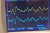
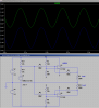
Each of the op amps shown in the attached circuit diagram is powered from differing rails (+, gnd and gnd, -) to produce two identical, but DC shifted, outputs.

In addition, the input signal is referenced to the negative rail instead of ground. There is a reason for this relating to balanced battery drain.

I tried adjusting the offset to each amp with R2, R3 and R7, R8 but canot bring it within range. Can anyone please offer a solution?

The final circuit will probably use LM358's.
 

Attachments

  • offset_op_amps.png
    offset_op_amps.png
    62.5 KB · Views: 236
It would be better if you posted your asc file. Try powering the opamps from the edge rails, I think then it should work correctly.
 
As requested, here is the .asc file.

Not sure what you mean by "edge rails".
 

Attachments

  • Dual Polarity Driver LM358 -2V Input.asc
    2.4 KB · Views: 211
Like this
 

Attachments

  • Dual Polarity Driver LM358 -2V Input2.asc
    2.4 KB · Views: 208
If the input signal really needs to be centered about -4.5V, then you will need to add a level shifter to move it within the common mode range of the opamps.
 
Yes, that works with a few resistance changes. But in your .asc you changed the return on the signal input to ground. How can I make the circuit work with a return to the negative rail as originally drawn? There is a reason I would like it this way. Thanks.
 

Attachments

  • Dual Polarity Driver LM358 -2V Input2.asc
    2.4 KB · Views: 192
If the input signal really needs to be centered about -4.5V, then you will need to add a level shifter to move it within the common mode range of the opamps.

I tried this with a divider across the rails to pin 3 of each amp but could not get it to work. Not enough adjustment possible by simply changing the resistor values. Would you have a sample circuit?
 
What exactly is the input signal? Maybe you could couple it with just a capacitor.
 
Bump. Can anyone offer a solution to the circuit in my OP?

The signal generator (not shown) and two op amps are powered from a simple voltage divider off a 9V battery. Current draw must be balanced to keep the rail voltages equal. Hence the genrated signal fed into the op amps is referenced to -4.5V instead of ground, but the amps are powered separately from each leg of the divider.

Basically, I need two op amps with adjustable input level shift and amplification. Nothing I have tried has worked so far.

https://www.electro-tech-online.com/attachments/offset_op_amps-png.110756/
https://www.electro-tech-online.com/attachments/dual-polarity-driver-lm358-2v-input-asc.110758/
 
Really? Maybe, just maybe, if you answered my questions I would provide you with what you want to know.
So I guess I will have to ask again: What is the signal generator doing? What voltage is that signal and what freqency or is it a DC signal? Does the signal go below the -4.5V rail?
Why not just show the generator? Why don´t you use an opamp for the virtual ground and stop worrying about balanced loading? What is the goal of the complete circuit?
 
The signal is a 3Vpp 10Hz sine wave referenced to the -4.5VDC rail. It does not go below the -4.5VDC rail.

The "generator" is a SOMO 14D module that plays back from a micro SD card. It is powered by 3.3VDC from a 5VDC regulator with two diodes in series. The regulator's common is -4.5VDC which explains why the SOMO 14D's signal is aslo referenced to that rail and not ground.

This is a battery powered circuti. I prefer to keep the component count low, e.g. without added active parts.

The circuit is intended to drive a magnetic coil through the 220R curent limiting resistor. Apart from that, I would like to learn how to implement a DC level shift in a situation such as described above.
 
This I think should be what you want, but might need some tweaking of the output offsets to get the output offsets you want.
 

Attachments

  • Dual Polarity Driver LM358 -2V Input3.asc
    2.6 KB · Views: 198
Here is the end result. Pretty good I would say, thanks to your help.
 

Attachments

  • dual_polarity_amps_breadboard.jpg
    dual_polarity_amps_breadboard.jpg
    158.2 KB · Views: 201
  • dual_polarity_amps_output.jpg
    dual_polarity_amps_output.jpg
    147.6 KB · Views: 208
  • dual_polarity_amps_schematic.png
    dual_polarity_amps_schematic.png
    51.3 KB · Views: 207
I am glad glad that we worked it out in the end. Also i would suggest getting some high efficiency step-down converter to power that SOMO 14D, otherwise you are wasting a lot of power on the linear regulator and drop diodes.
And i am sure there will be a lot of better choices for the amplifier than LM358, 1 to 2mA is quite a high static current for being powered by a 9V battery.
 
Status
Not open for further replies.

Latest threads

New Articles From Microcontroller Tips

Back
Top