Continue to Site

Welcome to our site!

Electro Tech is an online community (with over 170,000 members) who enjoy talking about and building electronic circuits, projects and gadgets. To participate you need to register. Registration is free. Click here to register now.

  • Welcome to our site! Electro Tech is an online community (with over 170,000 members) who enjoy talking about and building electronic circuits, projects and gadgets. To participate you need to register. Registration is free. Click here to register now.

OTL tube headphone amp

Status
Not open for further replies.

ian mason

New Member
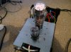
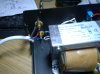
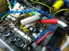
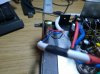
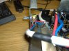
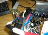
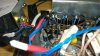
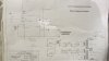
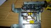
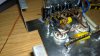
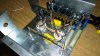
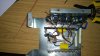
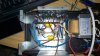
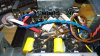
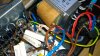
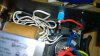
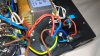
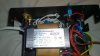
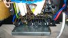
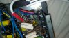
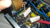
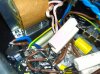
Started a new thread as well as posting to the old one, my apologies if I wasn't supposed to. Hi again all, thanks for all of your input last time, I have now finished the build having followed the schematic to the letter as it were but unfortunately it is not working and I just
wondered if anyone could spot any glaring mistakes from the ridiculous amount of photos that I have uploaded, I am a bit of a novice and I do realise that this project is
a bit beyond my capabilities but I have started and I'm now eager to hear the results, better still would there be anyone that is close to London, Uk, that could take a look
for me, happy to buy you a pint or two, the problem I have is that I don't really know where to start with the diagnosis and I'm not comfortable working with these kind of
voltages until I further my electronics knowledge, all replies are very much appreciated and thanks in advance. Also, should I have started a new thread.
Thanks Ian
 

Attachments

  • IMG_2457.JPG
    IMG_2457.JPG
    1.8 MB · Views: 139
  • WP_20171130_003.jpg
    WP_20171130_003.jpg
    1.8 MB · Views: 122
  • WP_20171130_004.jpg
    WP_20171130_004.jpg
    1.7 MB · Views: 143
  • WP_20171130_005.jpg
    WP_20171130_005.jpg
    1.9 MB · Views: 128
  • WP_20171130_006.jpg
    WP_20171130_006.jpg
    1.8 MB · Views: 123
  • WP_20171130_007.jpg
    WP_20171130_007.jpg
    1.8 MB · Views: 128
  • WP_20171130_008.jpg
    WP_20171130_008.jpg
    1.8 MB · Views: 144
  • WP_20171130_009.jpg
    WP_20171130_009.jpg
    1.9 MB · Views: 118
  • WP_20171130_010.jpg
    WP_20171130_010.jpg
    2 MB · Views: 120
  • WP_20171130_011.jpg
    WP_20171130_011.jpg
    1.5 MB · Views: 125
  • WP_20171130_012.jpg
    WP_20171130_012.jpg
    1.6 MB · Views: 128
  • WP_20171130_013.jpg
    WP_20171130_013.jpg
    1.3 MB · Views: 121
  • WP_20171201_001.jpg
    WP_20171201_001.jpg
    836.6 KB · Views: 129
  • WP_20171201_002.jpg
    WP_20171201_002.jpg
    583.2 KB · Views: 122
  • WP_20171201_004.jpg
    WP_20171201_004.jpg
    729 KB · Views: 123
  • WP_20171201_005.jpg
    WP_20171201_005.jpg
    1.7 MB · Views: 128
  • WP_20171201_006.jpg
    WP_20171201_006.jpg
    1.7 MB · Views: 117
  • WP_20171201_008.jpg
    WP_20171201_008.jpg
    1.7 MB · Views: 127
  • WP_20171201_009.jpg
    WP_20171201_009.jpg
    743.3 KB · Views: 125
  • WP_20171201_011.jpg
    WP_20171201_011.jpg
    837.8 KB · Views: 127
  • WP_20171201_012.jpg
    WP_20171201_012.jpg
    826.9 KB · Views: 118
  • WP_20171201_013.jpg
    WP_20171201_013.jpg
    1.6 MB · Views: 125
  • WP_20171201_014.jpg
    WP_20171201_014.jpg
    660.9 KB · Views: 121
  • WP_20171201_015.jpg
    WP_20171201_015.jpg
    1.3 MB · Views: 136
  • WP_20171201_016.jpg
    WP_20171201_016.jpg
    1.3 MB · Views: 127
  • WP_20171201_017.jpg
    WP_20171201_017.jpg
    884.2 KB · Views: 124
  • WP_20171201_018.jpg
    WP_20171201_018.jpg
    721.7 KB · Views: 133
Well check that the valves have a few ohms between the ends of the filaments. I think that they are pins 7 and 8.

Unplug the valves and check that you have around 6 V ac between connections 7 and 8 of the valve bases. You can turn the multimeter to Vac, put the multimeter leads into the valve base holes 7 and 8, step back, turn on the power and observe the reading.
 
Any particular reason why I am stepping back, what's the worst case
Worst case is that you have the transformer connections wrong, or you put the multimeter probes into the wrong connector, and you get big voltages, which you don't want to touch.

Insulated probes on the multimeter should be enough, but there is no need to be touching anything when you take the readings, so play safe. You said you were concerned about fault-finding with big voltage stuff, quite rightly, so I was just helping with methods that don't risk meter leads slipping etc.
 
Looking through your pictures, the heater connections on the valve bases look quite bad.
See my comments in the attached picture.

JimB

Amplifier solder joints.png
 
would there be anyone that is close to London, Uk, that could take a look
for me
If you have not sorted it by then, I will be in London from the 18th to the 20th of this month and would be happy to have a quick look for you.

JimB
 
Thanks JimB, I was looking at that as a possibility and I was having real trouble soldering those wires, I will give it a go but if no joy I would love to take you up on your offer, I will report back.

Thanks Ian
 
Thank you to everyone for all of the help, thanks to you the valves are now glowing like the sun, there were two problems, one was that the 2 resistors were not in p3 and p6, they were wrongly attached to the two 1000uf/ 300v and the second problem which was highlighted was that the 6.3v windings were not making a good contact with the valve pins.
However a new problem has arisen, I now have a dreadful hum (very loud) coming through the headphones, please could anyone tell me if I have wired anything wrong with regards to the audio connections, as usual I have added photos. Thanks again the progress feels rewarding.
 

Attachments

  • WP_20171202_002.jpg
    WP_20171202_002.jpg
    1.2 MB · Views: 116
  • WP_20171202_004.jpg
    WP_20171202_004.jpg
    1.4 MB · Views: 110
  • WP_20171202_005.jpg
    WP_20171202_005.jpg
    1.7 MB · Views: 114
  • WP_20171202_009.jpg
    WP_20171202_009.jpg
    1.5 MB · Views: 112
  • WP_20171202_011.jpg
    WP_20171202_011.jpg
    1.4 MB · Views: 115
  • WP_20171202_014.jpg
    WP_20171202_014.jpg
    1.4 MB · Views: 106
  • WP_20171202_018.jpg
    WP_20171202_018.jpg
    1.7 MB · Views: 114
I now have a dreadful hum (very loud) coming through the headphones
OK

1 Disconnect any input signals, turn the volume control completely down. Is the hum still there?

2 If there is still hum when volume is at minimum, remove the 6SN7. Is the hum still there?

JimB
 
1 The hum is still there with the volume turned down, I gather that by disconnect the input signals that you mean just remove the external rca lead and not desolder the rca terminals.

2 The hum becomes very slight with the 6SN7 removed only audible with the headphones on but with the tube in place it is very audible even without the headphones on.
 
I gather that by disconnect the input signals that you mean just remove the external rca lead and not desolder the rca terminals.
Yes.

Now lets look at the white cable which runs from the RCA connectors to the volume control and on to the 6SN7.

The screening braid of that cable, does it make a good connection to the chassis somewhere near the 6SN7 ?

Also, there appears to be something odd about the RCA connectors, they appear to be insulated from the chassis by white (Teflon/nylon) washers.
My conventional wisdom says that they should be connected to the chassis, although the designer of the amplifier may have other ideas.
Amplifier RCA Connectors.png


Have a look at the volume control, there should be a connection between the two cable screens at the anticlockwise end of the control.
Amplifier volume pot.png


JimB
 
Hum is the bane of valve amplifiers. Using twisted pair wiring to the valve heaters can help to reduce it.
 
Hum is the bane of valve amplifiers. Using twisted pair wiring to the valve heaters can help to reduce it.
Very true.
The heater wiring between the two valve holders leaves a lot to be desired, but lets try and sort the BIG hum first.

JimB
 
I have now removed the plastic washers and joined the screen wires together, I have joined the screen wire form the valve end to ground near to the 6SN7, are the 6.3v windings supposed to also be grounded
from the tube pins 7 and 8.
The hum still remains, could it be the transformer
 
The hum still remains
Is this still the loud hum which can be heard when the headphones are "on the bench" ?

Is the hum the same level in both ears of the headphone?

Have a look at the negative side of the power smoothing capacitors.
Are they connected to the metal chassis?

could it be the transformer
Stray magnetic fields from transformers can and do cause hum in audio circuits.
However in this case I think that there is something else happening to cause high levels of hum.

are the 6.3v windings supposed to also be grounded
It is common practice to let the 6.3v supply "float" above ground.

The wiring between valve bases is usually done with twisted wiring, in the style of the wiring that you have used from the transformer to the bridge rectifiers, the twisted wiring being run close to the metal chassis.

In one of your earlier pictures showing the early stage of assembly, the 6.3v heater wiring routing is about as bad as it could be!

JimB
 
The hum is still the same from both ears and cab be heard from the bench, once again forgive my ignorance but which ones are the power smoothing
capacitors, the wiring is a bit better now but still not great, those wires are very stiff and not easy to work with, could I cut them near to the transformer
and solder new wire to the remaining ends (after removing enamel of course) or this bad practice.
 
which ones are the power smoothing
Amplifier capacitor functions.png


those wires are very stiff and not easy to work with, could I cut them near to the transformer and solder new wire to the remaining ends (after removing enamel of course) or this bad practice.
The 6.3v wires out of the transformer are solid single core wire and will be quite stiff, as you have found.
It would be in order to shorten the wires from the transformer and to use stranded wire to make a twisted pair to connect to the valve bases.

JimB
 
Status
Not open for further replies.

Latest threads

New Articles From Microcontroller Tips

Back
Top