Continue to Site

Welcome to our site!

Electro Tech is an online community (with over 170,000 members) who enjoy talking about and building electronic circuits, projects and gadgets. To participate you need to register. Registration is free. Click here to register now.

  • Welcome to our site! Electro Tech is an online community (with over 170,000 members) who enjoy talking about and building electronic circuits, projects and gadgets. To participate you need to register. Registration is free. Click here to register now.

oscilloscope

Status
Not open for further replies.

Lighty

New Member
Hi all

I wonder if you can help, I have a Top Tronic oscilloscope, I know its another make thats just been re-branded, but can't remember the name.

I once had a problem where there was arcing on a "surface crack" on the board by the HV transformer output, it had gone black, so I scratched it clean and used laquer to seal it up again, I had to also replace the the D880 transister and the UA741CN IC that drives the transformer (If I remember correctly), and it worked for ages, but now its dead again.

I tested for voltage before and after the D880, and there was so its ok, but I changed it to be certain, and there is power on the input side of the transformer, but doesn't appear to be on the output side, but am not 100% certain, as I have no means of testing. I looked into the back of the tube for a orange glow, but can't see anything, should there be a glow?

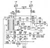
heres the reading of the transformer.

What else can I do?
 
Some CRTs filiaments are powered from the high voltage transformer secondary winding. If the transformer is not working you won't get filament glowing. Many HV CRT circuits need the exact transistor replacement, not a general replacement equivalent.

I tested for voltage before and after the D880, and there was so its ok, but I changed it to be certain, and there is power on the input side of the transformer, but doesn't appear to be on the output side,
I don't quite follow your statement that I underlined. Just cause there's voltage there doesn't mean things are working properly. Do you know what the voltages specs. should be? Do you have any H-drive entering that stage?
 
Hi HiTech

Thanks for the reply.

I have since found that there is a problem with the transistor driving circuit, Like you said, "Just cause there's voltage there doesn't mean things are working properly", I found the transistor getting extremely hot very quickly.

I unfortunately don't have any specs at all, would make like so much easier.

H-Drive........ sorry, but you have lost me.

It seams the transistor is not "pulsing" but staying "active", but its only my suspicion, if I had another scope I could test.....
 
Last edited:
The high voltage section is driven by a specific sweep signal. If that is missing the HV will not happen = no high voltage generation and thusly no other secondary operating voltages that stem from the HV transformer to operate other circuits in the scope. Of course this all depends upon the scope's design. It may likely have a power supply that generates most of the necessary voltages on its own, including the filament voltage.
 
Hi All

After shelving this repair for some time I'm back on it as I'm needing my scope and can't afford to buy another.

I've been searching quite a bit on the net and have come across the schematic of the HV supply circuitry.

The problem is that the CRT is dead, and there is no HV output from the transformer. I found that Q950 (D880) is frying, getting so hot it melts the plastic insulation washer.

I've also changed U950 (UA741CN) but with no luck.

I've removed the transformer and got the following resistances. Pin1-Pin4 = 0.3Ω, Pin4-Pin5 = 1Ω, Pin6-Pin8 = 330Ω, Pin10 is not used and is left open.

I'm getting all the right voltages (+12, -12) where they need to be.

My theory is as follows:

Although the very low resistance of the transformer inputs, I'm sure its driven at high frequencies therefore the impendence will reduce the current load. I think the circuit is not oscillating and therefore the low resistance is shorting through the D880 and causing it to burn, But I'm not sure? :confused:

I'm not sure where or what to check now? Which part of the circuit causes the oscillation to drive the D880?

I would really appreciate some help or guidance, as I really need to get this scope working.

Just one note on the schematic, C957 is not on the board, and there has never been a component soldered in there.

Thanks in advance!

Justin
 
The Schematic

Sorry, forgot to add the schematic.

I believe the scope is a copy of many other re-branded scopes. Like the following (indentical)

**broken link removed**

Thanks
 

Attachments

  • scope1.jpg
    scope1.jpg
    69.6 KB · Views: 567
It looks like a crude 'blocking oscillator' so there's only the output transistor and the transformer. The 741 is used to monitor the output and adjust it to be correct.

Most likely problem is the transformer, which may have failed 'shorted turns'
 
Thanks Nigel.

Is there any way of testing the transformer to confirm? and if it is, could an new one be made up without have the specs for it? would there be any other way of powering the HV side?
 
Some years ago, I recall seeing a "Shorted turns tester" in a magazine, possibly Silicon Chip.

So I'll look at my SC index & let you know.

You could also try an internet search.

EDIT. It is in the Feb 2004 issue.

I'll scan it and post later.
 
Last edited:
I have scanned the page that has the circuit diagram.

I'll scan the rest of it for you if you wish.

They describe the theory of operation, construction & testing and explain how to wind a test coil.
 
Thank for your help Nigel and ljcox, I will build the circuit now and test the transformer.

Can one test the circuit on a normal 50hz tranformer to ensure its working?
 
Ok, I've built the circuit on breadboard and when I power up LED1 lights up.

So I tested the circuit with a spare 220 - 15V tranformer on its 15V side, and ALL LEDs burn, but when testing the 220V side only the one LED burns.

I then tested the HV transformer from scope (removed from board). When I tested between any of the 3 pins on the input side the LED goes off. when I test the output side I got 2 LEDS.

From what I read and understand this tester it's only used to test the ouput side of the transformer? does it make any difference if its as a step up or step down transformer?

Is this tester good for higher Hz transformers?

Thanks

Justin
 
Do you want me to scan the part of the article that outlines the testing procedure & how to wind a test coil?

Since Nigel has had experience with using it, his answers to your questions will be valuable.
 
Here are the 2 relevant pages.

I have to go out shortly, so I'll post the rest later.

Page 68 has comments by people who tested the unit for the author.
 
From reading the articale, it appears my coil is cooked :(

Trying to get another coil wound would be nearly imposible here in South Africa, so what other options / plans could I make? would a small flyback transformer from a small B&W monitor not work, not sure on the voltages of these types of units? There must be something :(
 
Could you rewind it yourself?

Here are the missing pages.

Nigel may have some ideas.

I'll have start another post for the last page.
 
Status
Not open for further replies.

Latest threads

New Articles From Microcontroller Tips

Back
Top