Continue to Site

Welcome to our site!

Electro Tech is an online community (with over 170,000 members) who enjoy talking about and building electronic circuits, projects and gadgets. To participate you need to register. Registration is free. Click here to register now.

  • Welcome to our site! Electro Tech is an online community (with over 170,000 members) who enjoy talking about and building electronic circuits, projects and gadgets. To participate you need to register. Registration is free. Click here to register now.

Oscilloscope problem

Status
Not open for further replies.

large_ghostman

Well-Known Member
Most Helpful Member
Hi All,
Sorry for asking this but, I purchased a Gould DSO 400 for Jason. It was what he had been hopeing to get for Christmas. It arrived today and both Logan and someone that works here on the farm have had a good look at it. Apparently it's not working as it should.
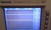
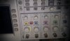
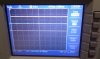
All i know is they can get the screen to display menu's etc but it will not show a "trace"?? i am sorry this is so vague but i just have no idea what they mean. So if there is anyone that thinks they could repair this fairly cheaply for us i would be grateful. i will obviously pay postage and cost for parts and your time, i would be able to post pictures of the screen if that helps. We cant afford much but i would love to have it working for him if i could, so does anyone have a rough idea what it will cost to repair?

Many thanks
Rachel xxx
 
I will take some pictures this evening. also i have managed to get a operators manual so will give that a shot as well.
 
Scopes can be triggered or free running. If it is in the triggered mode you will not see a trace without a signal.

Look for some way to set it into a non trigger or free running state.

You may have to adjust the vertical position of the trace to see it.
 
Thank you 3v0, we have tried all modes, and followed steps in the manual, in the manual it says that in auto it always tries to go into DC mode if it can. On this one it always defaults to AC, we have tried the cal tag? on both this oscilloscope and another one and also tried a 5v something??? (i am passing info on)
here are some pics i am not sure if they show anything useful.
a couple of the men that work here have tried with Logan and everyone is convinced there is a fault as they can easilly get a TRACE?? up on the other Oscillscope. i think at this point i would rather send it to someone and pay them to check it over and get it going.
11127-26-01-2011 18-19-40.png


11128-26-01-2011 18-21-19.png


11130-26-01-2011 18-22-13.png


11129-26-01-2011 18-22-51.png
 
Last edited:
Did you purchase it new or second hand?

It does look like it isn't working properly, I can see you have DC coupling on and if you connect it to a 5V and set the V/DIV (volts per division) to 1 Volt you should see a line roughly 5 squares above the center point.

You would also expect to see a solid white line indicating 0v.

Make sure that the trace hold isn't on and that you have the scope in auto / running mode, and also make sure that the CH1 probe is set to "display", as you can turn the trace on and off and even use a math function on some scopes.

Regards

Wilksey
 
Hi Wilksey
the scope was second hand from ebay. We have tried all your sugestions with no luck :(
 
Hi 3v0 i have tried that approach and looks like we are stuck with the scope. I have searched the Web for places i could send it too for a repair but no luck as yet. VERY VERY upsetting to say the least!!
 
Hi Rachel,

IMAG0041.jpg as attached shows the basics of my scope, it is a 200MHz Tektronix DSO 4 channel. You will see the 2 "wavy" lines (traces), these are yellow and blue,You will also see up the top of the screen R Auto, this means it is running and in auto mode.

I then set the probe to 10x, DC Coupling and measured a 5V supply from an external power source. Using the cursor mode of the scope I could exact the voltage level, look at IMAG0043.jpg, you will notice that the first cursor for channel 1 is at 0v (this is the offset of channel 1 also, hence the "1" by the yellow line). You will notice that Cursor 2 is set at just above 5v and the wavy trace line has moved up. If you look at the bottom of the screen you will see that the V/DIV is 2V per division, hence the 2 1/2 "sections" before the trace line which is 2 divisions = 4V plus half a division = 1V, in total = 5V, and the cursor measures 5.12V which is within spec, you can also see that the cusor source is set to voltage and is set to Channel 1.

IMAG00042 shows the majority of the instrument panel of my scope.

Mine has a probe comp "tag" which will detect and auto set up the probes for the correct settings, mine are set to 10X.

Hope you can decipher some of that! lol

Wilksey
 

Attachments

  • IMAG0041.jpg
    IMAG0041.jpg
    1 MB · Views: 258
  • IMAG0042.jpg
    IMAG0042.jpg
    746.4 KB · Views: 254
  • IMAG0043.jpg
    IMAG0043.jpg
    1.1 MB · Views: 229
I have a BK2120 and it will not work right if you do not start it just like the manual tells you. But it worked fine after I found the startup setting in there manual
 
Thank you be80be, we have tried all the steps in the manual have not seen any sign of a trace!
 
I will probaly throw the bloody thing on the skip!
 
Hi Rachel / Logan,

On the very last page of the operators manual that I downloaded is information on how to perform a full system reset, it may be worth a try if not already done. It should force a full self calibration and reset any previous setups, if the self calibration fails it may give a clue to what is wrong.


400 Operators Manual Amendment Sheet November 1990
400 System Reset
Should the system memory become corrupted, the instrument could lock out the front panel operation or begin to behave erratically. Since the internal system variables are held in non-volatile memory, turning the set off an on again may not clear them. In this unlikely event a system reset may be necessary.
A system reset should only be used as a last resort as all the internal memories will be cleared erasing all reference traces, calibration details, and set-up details.

To perform a system reset, switch the instrument off. Press and hold the Hold All and the Plot buttons. Keep these buttons pressed and turn the instrument on using the Power button. The instrument will then start up in its reset condition. This can be confirmed by noting that on power up the instrument performs a complete calibration.

Amendment to 400 series Operators Manual Part Number 457403
Page 1


Regards,

Leftfield95
 
Hi all. I just tried the above steps but to no avail, the machine went through it's thing but afterwoods still no trace no matter what i did. But one thoing i have noticed, i tried to get a trace on the old oscilloscope using the little cal tab thingy and managed to get a trace up on it so i connected the new scope to the old scopes tab but no luck, however out of curiosity i tried connecting the old scope to the new ones little cal tab. Both little tabs say 1v.
on the old scope when i connect to its tab with its own probe it reads 1v but when i connect the old scope to the new ones little tab it reads -0.7??? surely that cant be right? would a fault like this mean there is a reason why no trace?
Sorry if i havnt explained it very well but i am having to learn something i have no interest in very very quickly so i can try and get this thing working. I have decided if i havn't made progress by tommorow afternoon then the scope is scrap :(
Thank you for the help everyone
 
Status
Not open for further replies.

Latest threads

New Articles From Microcontroller Tips

Back
Top