Continue to Site

Welcome to our site!

Electro Tech is an online community (with over 170,000 members) who enjoy talking about and building electronic circuits, projects and gadgets. To participate you need to register. Registration is free. Click here to register now.

  • Welcome to our site! Electro Tech is an online community (with over 170,000 members) who enjoy talking about and building electronic circuits, projects and gadgets. To participate you need to register. Registration is free. Click here to register now.

Oscillator troubles

Status
Not open for further replies.

excetara2

New Member
I am working on a beat frequency oscillator metal detector. The rest of the project is working properly. The mixer, filter, daq modules, and such.

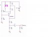
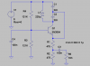
I can't manage to get this oscillator working. It is a simple oscillator. The only difference on the other one to produce the frequency is I wind my own coil. Neither of them oscillate at all. Any ideas or something to try to change. Schematic of one oscillator attached.

Sorry, 220uH is the inductor if not visible.
 

Attachments

  • oscillatoroneschematic.JPG
    oscillatoroneschematic.JPG
    23.8 KB · Views: 197
An obvious ommission is the decoupling capacitor on the base of the transistor - it's not likely to work without that (I'm assuming you have a decoupling capacitor across the power rails?).
 
Try something like 0.01uF, it's also vital in all circuits to have decoupling capacitors across the supply rails, try a 0.01uF and a 100uF in parallel (an electrolytic is VERY important on battery powered items).
 
Placed both in the circuit to no avail. Should I try another oscillator. I believe the desing is right. It worked in pspice.
 
Please show us some of your simulation results, like op points and waveform.

Your design shows only flatline output when I simulated it in LTSpice. Adding capacitors to transistor base did not help neither.
 
All my simulations seem to be working, maybe there's something
wrong with (me or) my simulator. :D

on1aag.
 

Attachments

  • Excetara I schematic.PNG
    Excetara I schematic.PNG
    16.3 KB · Views: 170
  • Excetara I FFT.PNG
    Excetara I FFT.PNG
    21.2 KB · Views: 170
  • Excetara II schematic.PNG
    Excetara II schematic.PNG
    16.1 KB · Views: 156
  • Excetara II FFT.PNG
    Excetara II FFT.PNG
    18.5 KB · Views: 168
  • Fet 100khz osc. schematic.PNG
    Fet 100khz osc. schematic.PNG
    15.3 KB · Views: 171
  • Fet 100 khz osc FFT.PNG
    Fet 100 khz osc FFT.PNG
    17.3 KB · Views: 174
on1aag said:
All my simulations seem to be working, maybe there's something
wrong with (me or) my simulator. :D

on1aag.

My inexperience in using simulator. :p

It turns out I just use the ".tran 0 20m" .op command the circuit does not seem to oscillate. See image. However, it oscillates normally after I added the extra parameters similar to yours.

Why would ".tran 0 20m 0 1u" make such a big difference?
 

Attachments

  • sim_error.gif
    sim_error.gif
    19.6 KB · Views: 152
You can usually get an oscillator to start immediately by adding the initial condition directive
Code:
.ic i(L1)=1u
or something similar, to your schematic.
You can also usually get it to start by switching your power supply on rapidly
Code:
PWL(0 0 1u 9)
instead of assigning it a DC value.
BTW, this circuit oscillates in simulation without the base bypass cap.
 
Last edited:
Thanks Ron.

Tried the above simulation with each of your suggestions and the oscillator now starts up every time.
 
Nigel Goodwin said:
But would you ever build a common base circuit without one? :D
I probably wouldn't have even considered the possibility that it might work without one.
 
Status
Not open for further replies.

Latest threads

New Articles From Microcontroller Tips

Back
Top