Continue to Site

Welcome to our site!

Electro Tech is an online community (with over 170,000 members) who enjoy talking about and building electronic circuits, projects and gadgets. To participate you need to register. Registration is free. Click here to register now.

  • Welcome to our site! Electro Tech is an online community (with over 170,000 members) who enjoy talking about and building electronic circuits, projects and gadgets. To participate you need to register. Registration is free. Click here to register now.

Optocoupler calculation

Status
Not open for further replies.

gert123

New Member
Hi all,
I have this circuit (see attached) and would like to calculate when the optocoupler is in saturation and the cutoff frequency of the filter. I would like to do this in order to design that a specified amount of current has to flow before it’s registered by the microcontroller in order to eliminate noise.

Thanks in advance
 

Attachments

  • opto.pdf
    6 KB · Views: 387
Hi all,
I have this circuit (see attached) and would like to calculate when the optocoupler is in saturation and the cutoff frequency of the filter. I would like to do this in order to design that a specified amount of current has to flow before it’s registered by the microcontroller in order to eliminate noise.

Thanks in advance

hi,
I assume that to turn ON the opto emitter you plan to connect J1/1 to 0V.??? This will limit the current to the emitter to ~ 1mA which is not high enough to turn ON the emitter.????
 
To me that circuit is overly complicated for what is essentially a digital input.
(At least I hope it is intended as a digital input, if the OP is trying to use it for an analogue input I think he is in for a dissapointment).

I would simplify the circuit as attached, the "filter" in the original circuit will not have much effect as the (digital) input is either open or short circuit.

JimB
 

Attachments

  • Simplified Opto.PNG
    Simplified Opto.PNG
    10.6 KB · Views: 456
Well essential yes but its connected to 0V with a load, and depending on the load i want to get a digital 0 or a 1. The reason for the pull up is that the load may requires 20mA.
 
Hi JimB,

Thanks for your input the reason for the construction is that the connector might me connected to a real switch. Which might be 50m away and there for form an antenna with a lot of noise when the switch is not grounded. Too make sure that the optocoupler first switched on when a current of 10mA or more is connected as a load I want to calculate the saturation and still make sure that the filter has a good enough cut off frequency.

So if you could help me with the thevenin equation it will me much appreciated.
 
Well essential yes but its connected to 0V with a load, and depending on the load i want to get a digital 0 or a 1. The reason for the pull up is that the load may requires 20mA.
What is the "load"?
You seem to be trying to use this circuit as a comparator to switch at some load current.
This scheme will at best be unreliable, and in all probability will fail badly.

The current transfer ratio of the opto-coupler is not well defined, it has a broad spread from device to device and is probably temperature dependant.

If you want to switch something depending on the current in your load, use a properly designed circuit to measure the current and a comparator to decide the switching point.

JimB
 
the load may requires 20mA
when a current of 10mA or more is connected as a load
You are blowing my mind! This is inconsistent and vague.

What is the "load"?

What are you trying to do?

JimB
 
Hi Jimb,

Sorry for not being clear. Your right the best solution would be to use a comparator but I don’t have space for that. I tried the schematic and it works but not with the right current load, it’s probably R3 I have to adjust but I want to calculate so I know that the power dissipation is to high and ect.

The load is a real switch.

Your right this circuit will be very temperature depended, but its on noise from an antenna I’m trying to get rid of so a precise current switch is not needed.

thanks in advance.
 
Last edited:
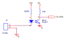
OK, looking at my circuit in post#3.

The input to the CPU has a 10k pull-up to 5v.
When the opto is off, there will be 5v at the CPU input. (lets call this the "1" state")

In the "0" state, lets say we want 0.5v at the CPU input, so we must drop 4.5 volts across the 10k resistor.
4.5v across 10k means that 0.45mA must flow in the resistor, and through the transistor side of the opto.

Looking at the datasheet for the opto, it has a current transfer ratio (CTR) between 80% and 600% depending on the exact model of opto.
Let us assume a CTR of 100%. So to have 0.45mA flowing in the transistor, we must have at least 0.45mA flowing in the diode.

In my circuit I just set the resistor in the diode side of the opto at 560 Ohm.
There is a 12v supply, so when the input is short circuited by the switch the current flowing in the diode will be about (12 - 1.5)/.56 = 18.8mA. (The 1.5v in the calculation is the diode forward voltage drop).
The opto will be well and truely saturated.
We could increase the value of the 560 Ohm resistor quite considerably and still be well saturated.
Lets make it 4.7k so we get (12 - 1.5)/4.7 = 2.2mA in the diode.
The circuit should still work quite well, the opto will be saturated.


Noise on your 50 meters of wire.
There has to be a circuit, so we need two wires, one going out to the switch and one returning from the switch.
Are these two wires running together in the same cable?
If not, why not?
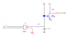
One of the most basic ways of minimising stray coupling to magnetic and RF fields is to run the go and return wires closely together.

If the wires must be separated for whatever reason, a simple re-arrangement of the circuit and adding a capacitor should fix it.

See the attachment below.

JimB
 

Attachments

  • Simplified Opto 2.PNG
    Simplified Opto 2.PNG
    14.5 KB · Views: 412
Status
Not open for further replies.

Latest threads

New Articles From Microcontroller Tips

Back
Top