Continue to Site

Welcome to our site!

Electro Tech is an online community (with over 170,000 members) who enjoy talking about and building electronic circuits, projects and gadgets. To participate you need to register. Registration is free. Click here to register now.

  • Welcome to our site! Electro Tech is an online community (with over 170,000 members) who enjoy talking about and building electronic circuits, projects and gadgets. To participate you need to register. Registration is free. Click here to register now.

opto isolated h bridge PCB design

Status
Not open for further replies.

ardv

New Member
i need to design a PCB for the h bridge with optoisolator, like that one:
a2.jpg

i have Proteus to design with, but i'm new to PCB design, i searched for a ready PCB design for that circuit in the net but i couldn't find.
i hope that you can help.
 
Last edited by a moderator:
That is a horrible H-bridge.

Try this search on these forums:
Keywords: shoot-through h-bridge
Posted by: MikeMl
 
The one I use regularly is this one... I know it doesn't use FET's but it works well for me..
http://www.mcmanis.com/chuck/robotics/tutorial/h-bridge/bjt-circuit.html
Its safe ( no shoot through ) easy to use... PWM on the ENA* line..

when designing this in PCB, i use the same schema? or there are things i should change in (i think the output of the circuit should not be in the middle)? and which program is easier to do this task? is Proteus good for this?
 
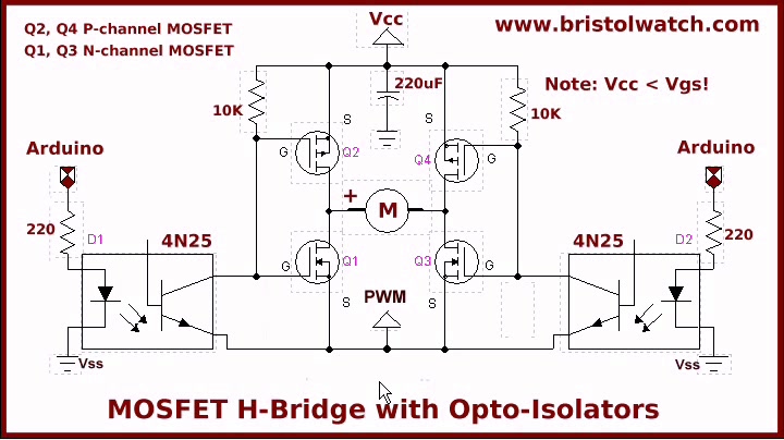
Note that you if you wish to use PMOSFETs on the high side, and are not using a floating gate driver then the maximum working voltage for Vcc is Vgs of your PMOSFET, not Vds like normal. Look at how much voltage appears on the gate pin when you pull it down to turn the MOSFET on and note the voltage difference between gate and source when that happens. Doing it this way usually limits your motor voltage to 10V (maybe 20V) due to availability of parts).

BTW, the only reason you would use a PMOSFET is to not need a floating gate driver. You would never use a PMOSFET with a floating gate driver because a floating gate driver would let you use a NMOS which is more efficient and readily available. Usually 20V is the highest voltage you can find for the gate-source voltage on a PMOS.

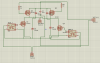
In your case, you are already using opto-isolators so if you added two more optos and zener diodes (to make a supply referenced to Vcc that dips below Vcc), you can use the opto along with that supply to make a floating supply for your high-side transistors which would let you use all NMOS.

I attached a sample schematic of what I am talking about but with a PMOS. Do you understand what's going on? The zener and resistor make a voltage regulator that dips below Vcc, and is referenced to Vcc (instead of ground) to provide a voltage between the source-and-gate pin of the PMOS. The opto is an opto so it can drive it just fine. But this circuit is a bit pointless because you can do almost the exact same thing to let you use an NMOS in the top transistors. I made this schematic in about 5 minutes so I might have missed or overlooked something. Don't use it blindly (technically don't use it at all. Modify it so it works with a NMOS).

Also, don't forget high-speed flyback diodes (like schottky diodes) in anti-parallel with each MOSFET drain-source, or your transistors may get damaged everytime current is interrupted across the motor inductance which will produce a large votlage spike if the current produced by the collapsing magnetic field has nowhere to circulate.
 

Attachments

  • PMOS Example.PNG
    PMOS Example.PNG
    69.3 KB · Views: 264
Last edited:
when designing this in PCB, i use the same schema? or there are things i should change in (i think the output of the circuit should not be in the middle)? and which program is easier to do this task? is Proteus good for this?
I use Proteus for everything... All my boards have been done with Ares....
 
i couldn't find irf4905 and irfz44n (which i have, and want to use in the circuit) in Proteus
For making PCB you only need the To220 package.. However... Both of those devices are in Proteus..
 
For making PCB you only need the To220 package.. However... Both of those devices are in Proteus..

edit1: is '4n35' the same as cnx35 in Proteus?

the components i already have to design my circuit: irf4905, irfz44n, CNX35.
 
Last edited:
All you do is check the pinouts.... If they are the same, 4n25 is a 6 pin dip.. Download the PDF's and make sure...
thank you, i found that it is the same.

i have some parts i want to use as inputs or outputs but i don't know their names in Proteus, i hope that you can help.
upload_2018-1-10_9-3-37.jpeg
 
that's what i managed to do, is the circuit design correct? and how to optimize this PCB?
 

Attachments

  • 01.bmp
    16.7 KB · Views: 181
  • 001.png
    001.png
    37 KB · Views: 342
that's what i managed to do, is the circuit design correct? and how to optimize this PCB?
No... Not by a long way...
upload_2018-1-10_9-36-49.png


But I still not happy with this design... It needs a big cap and resistors on the optocoulers... Also I would have thought, 100r on the gates..???? Someone else will know.

"Driving FET's isn't as easy as dustin crops boy!!"
 
No... Not by a long way...
View attachment 110128

But I still not happy with this design... It needs a big cap and resistors on the optocoulers... Also I would have thought, 100r on the gates..???? Someone else will know.

"Driving FET's isn't as easy as dustin crops boy!!"

thank you, i'll try this circuit and tell you if it works.
in the datasheet of those transistors, i found that there is integrated diodes, so i think i don't have to add them in the circuit.

how to make aligning the circuit components easy in Proteus?

"I don't think the design above lends itself to PWM." sorry i didn't understand this.
 
Last edited:
Status
Not open for further replies.

Latest threads

New Articles From Microcontroller Tips

Back
Top