Continue to Site

Welcome to our site!

Electro Tech is an online community (with over 170,000 members) who enjoy talking about and building electronic circuits, projects and gadgets. To participate you need to register. Registration is free. Click here to register now.

  • Welcome to our site! Electro Tech is an online community (with over 170,000 members) who enjoy talking about and building electronic circuits, projects and gadgets. To participate you need to register. Registration is free. Click here to register now.

optical switch and pics

Status
Not open for further replies.

max_imum2000

New Member
i was playing around with sloted optical switch, just a normal standard type.
i was trying to know exactly its output and if that i can connect it directly to a pic digital input.
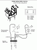
i wired the circuit in a simple manner ( attached ) to a 25Hz source (rotating wheel with holes connected to a motor)
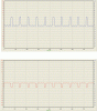
and when i connected a ociloscope to the signal out (channel A, blue) and ground (channel B, Red)
i noticed a strange behaviour the pulses from the signal out is ranging from -1v to 5.5v and the ground seems to be an inverse of it

now is that a normal behaviour ? and why ?
can this be connected to a pic directly or some sort of 555 or similar will be better in between ?

thanks
 

Attachments

  • img46.gif
    img46.gif
    15.8 KB · Views: 829
  • Graphic1.gif
    Graphic1.gif
    59.5 KB · Views: 197
You can connect it directly to a PIC without any problems, it's just a standard logic level. Your -0.1V is probably a measurement error, because you have the scope ground connected wrongly?.
 
Your scope is probably measuring the voltage drop across the ground wire?, caused by the LED current - don't use a single wire to return them - although it makes no difference at all to the function of the circuit.
 
ok, so i connected signal out to RB0 on a pic16f628A
set the ext interrupt on rising edge

tested the pic alone first by pulsing 5V to RB0 and display a counter on LCD
it works .

checked first that the optical switch is working

connected signal out to RB0 from the optical switch , connected common ground

then connected to RB0
nothing
the counter not increasing !!

optical switch works alone
pic interrupt counter works alone
they both wont work togther !

any help ?
 
ok , here is what i gut so far
i replaced the 2.2k resistore with a VR 1k
and started to reduce the resitance
when it reached about 60 ohms the pic started counting and detecting the Rb0 interrupt
i countected the motor with the same ps of the circuit (ie 5v)
now if disconenct the motor and rotate it by hand, counter stops
if i connect to to another PS (12V) to increase speed, it also stopped counting !
i am really lost here

the motor suppy is completly isolated form the circuit ps
so i think the motor speed is the factor here

any clue please
 
I don't understand what you are trying to do in the first post.

We do not connect another channel of the scope to see the ground signal. The signal's ground should also be the scope's ground. In fact you can observe only one signal in your optical switch test setup and that's channel A connected to the collector of the detector. And remember, label the axis of the trace image so others will know what they are. Therefore, the trace can at best showed that the optical switch works but not being correct about their voltage level.

Regarding your current difficulties, you'll need to post a circuit diagram of the connections from the optical switch to the PIC, before we can advise any further.
 
hmmm, got common grounds? (pic and opto?).

also, a 60 ohm pullup is way too low. should be more like 10K. given that you have to REALLY pull up the collector, I'd bet you have a source of light other than the LED. got proper shielding? some PTs don't have a daylight shield so it may be picking up room light.
 
Status
Not open for further replies.

Latest threads

New Articles From Microcontroller Tips

Back
Top