Hello Guys,
Nobody has an Answer?
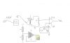
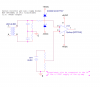
is it necessary to have a common ground between secondery side and opamp if i use it as differential amp?
because the difference schould be independent of ground, so i can use it without connecting secondary side of the transformer with the ground of the opamp right?
Yes, still necessary. Differential inputs only means that the MEASUREMENT is independent of ground. It doesn't mean that the signal is independent of ground. The internal function of the amplifier itself still needs currents to flow into the inputs and through ground and it still relates ground to the inputs in some way. An example of this is the way that the differential signal can't stray too far from ground or the amplifier won't work anymore, like how you can't apply 30V and 29V and still have the amplifier measure 1V because the common mode voltage at the differential inputs is too far away from ground.
Differential measurement just means that ground is not used as the reference in the measurement. It is not the same thing as saying ground is no longer needed. It's a bit like measuring the distance between the 3rd and 4rth floor of a building:
1. You can measure the floors with respect to ground and then subtract them to find their distance between each other (non-differential).
2. Or you can measure the distance between the 3rd and 4rth floor directly (differential measurement). The ground doesn't play a role in the measurement, but the ground still needs to be there for the building to sit on. Without the ground for the building to sit on, everything stops working.
If you're trying to measure the distance between the 499th and 500th floor, you might not be able to measure it at all even though your measuring tape is long enough to measure the distance between the floors directly (differential measurement) because you don't have a crane that can reach high enough for you to use your measuring tape (the diifferential input voltage is within op-amp limits but the common mode input voltage is too high).
Everything still depends on ground to function even though the measurement doesn't depend on ground and nothing is being measured with ground as the reference.
For it to be truly independent of ground, the differential inputs of the op-amp would have to be floating, which it is not.