Continue to Site

Welcome to our site!

Electro Tech is an online community (with over 170,000 members) who enjoy talking about and building electronic circuits, projects and gadgets. To participate you need to register. Registration is free. Click here to register now.

  • Welcome to our site! Electro Tech is an online community (with over 170,000 members) who enjoy talking about and building electronic circuits, projects and gadgets. To participate you need to register. Registration is free. Click here to register now.

open collector gates for wired-AND operation

Status
Not open for further replies.

PG1995

Active Member
Hi,

Could you please help me with this query? Thanks for the help!

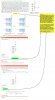
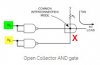
I understand that when two or more open-collector gates are combined, you get a wired-AND gate. But such a wired-AND gates has negative logic which means it gives HIGH output only when all its inputs are LOW. I agree with the expression on the right which says X=A'B'C'D' where A' means complement of A.

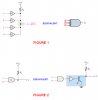
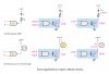
I do not understand why the author is using uncomplemented inputs to derive output expression in subsequent sections. Please see the green highlights where it is said that X=ABCDEFGH and X=ABCDEF.

Is there a mistake in the text, or is it just me? Please guide me.
 

Attachments

  • open_collector_wired_and.jpg
    open_collector_wired_and.jpg
    619.8 KB · Views: 207
The example is using AND gates (not NAND) so there is no inversion involved.

When all the AND gate inputs are high, all the outputs will go high (or rather open) allowing the pullup to set the output level high.
 
I don't think those are regular AND gates. Notice the symbol in middle of each 'AND' gate. Thanks.
 
Thank you!

But I don't think that I understand it. The following picture is from the link provided by KeepItSimpleStupid . Both inputs should be LOW to get HIGH at the output X. This is open-collector AND gate. I'm sure that the missing of word 'wired' doesn't make much of a difference.

X = (Input_1)' (Input_2)' where apostrophe denotes complement.

kiss_open_collector-jpg.117503
 

Attachments

  • kiss_open_collector.jpg
    kiss_open_collector.jpg
    7.5 KB · Views: 320
Those are NAND gates, not AND gates. The dot / small circle on the output represents a signal inversion.
With both inputs connected together they function as simple inverters, with open collector outputs (though they are missing the OC symbol).

With that configuration, both gates need the inputs LOW to give high (open) outputs.

See the various gate type symbols in the article here:
https://whatis.techtarget.com/definition/logic-gate-AND-OR-XOR-NOT-NAND-NOR-and-XNOR
 
Thank you!

From the discussion, the following is what I have concluded. A wired-AND configuration of inverters is different from open-collector AND gate. A wired-AND configuration of inverters works like a negative-AND gate. An open-collector AND gate has a transistor attached to its output. Please have a look on the picture below. Do I have it correct?

wired_and-jpg.117508
 

Attachments

  • WIRED_AND.jpg
    WIRED_AND.jpg
    46.1 KB · Views: 304
I think. You are confused about a Low output being different than no output. In logic speak, a Low is literally a connection to ground. Several of your circuit images are directly connecting a low output to a high output which will short out the output pins and cause catistrophic damage to the component.

02EFAEC8-C783-45E1-9EB6-9AFDA4F0256A.jpeg
 
Please have a look on the picture below. Do I have it correct?

Yes, I think you have it spot on correct.

An open collector TTL gate in effect is missing the upper half of the normal totem pole output, so only the pull-down transistor controls the output.
 
Have to take issue there Nigel.

An OR gate does not invert, a NAND does.

I don't think he meant that, I think some parenthesis were needed. NAND and NOT AND are the same thing.
 
Thank you!

Yes, I think you have it spot on correct.

To be honest, there is still confusion in my mind and most of it comes from how the author has, in my opinion, mixed up the stuff in the given section. Anyway, let's see.

An open collector TTL gate in effect is missing the upper half of the normal totem pole output, so only the pull-down transistor controls the output.

Yes, you are right. In open collector TTL inverter gate R3, Q4 and D2 are missing.

open_collector_rjen-jpg.117519


Do you really think that the circuit in FIGURE 2 is correct (Edit: FIGURE 2 from my previous post, post #8)? It says that a normal AND gate is connected to a normal inverter and then there is an open collector transistor attached to the output of inverter.

To get a NAND gate, as Nigel Goodwin pointed out, you can just connect an open collector transistor to the output of normal AND gate as shown below.

open_collector_nand-jpg.117521


Thank you.
 

Attachments

  • open_collector_rjen.jpg
    open_collector_rjen.jpg
    50.8 KB · Views: 254
  • open_collector_nand.jpg
    open_collector_nand.jpg
    67.1 KB · Views: 249
Last edited:
Do you really think that the circuit in FIGURE 2 is correct? It says that a normal AND gate is connected to a normal inverter and then there is an open collector transistor attached to the output of inverter.

To get a NAND gate, as @Nigel Goodwin pointed out, you can just connect an open collector transistor to the output of normal AND gate as shown below.

I don't know which is supposed to be figure 2.

An AND gate connected to an inverter with an open collector output is functionally the same as an AND gate plus a transistor (which inverts) to give the open collector output. Each gives NAND function.
(Remember that in reality the external transistor would need resistors between gate & base and base-emitter.)

If the first text refers to an open collector AND, then the double inversion is correct, to retain the overall AND function.
 
NAND to quasi OC NAND, all you need is a diode, cathode to gate output. Take the OC output from the Anode.

The output LOW is a bit higher voltage, but it works most of the time.
 
Status
Not open for further replies.

New Articles From Microcontroller Tips

Back
Top