Continue to Site

Welcome to our site!

Electro Tech is an online community (with over 170,000 members) who enjoy talking about and building electronic circuits, projects and gadgets. To participate you need to register. Registration is free. Click here to register now.

  • Welcome to our site! Electro Tech is an online community (with over 170,000 members) who enjoy talking about and building electronic circuits, projects and gadgets. To participate you need to register. Registration is free. Click here to register now.

Opamp Single Supply - TL072

Status
Not open for further replies.
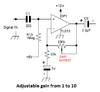
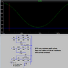
I would not think so; the maximum DC gain is with the bass control at one extreme, so around 11:1

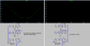
Even if the opamps had several millivolts offset difference, it's still only going to affect the DC output level of the second amp by a fraction of a volt.
 
I have finalised the schematic for this tone control.Please check the errors & unwanted parts.
Add a connection dot to the left side of R4.
The correct reference designator prefix for an opamp is U.
Other than that, looks good to me.

Consider adding pin numbers to the IC symbols. Not a critical item, but they come in handy when using dual and quad parts, and are *really* handy when troubleshooting.

ak
 
Last edited:
The polarities for C5 and C9 are backwards. The inputs and outputs of the ICs are positive and the volume control R%12 is grounded.
It is best to use C6 to filter out hum and noise from the +12V and R13 to bias the opamp.
 

Attachments

  • opamp biasing.png
    opamp biasing.png
    52.9 KB · Views: 248
The polarities for C5 and C9 are backwards. The inputs and outputs of the ICs are positive and the volume control R%12 is grounded.
It is best to use C6 to filter out hum and noise from the +12V and R13 to bias the opamp.
Thanks.I will change the polarities of the C5 & C9. will that correct the signal ground issue?

Are you referring to which diagram.The final diagram is in post 9.Is that 47uF in wrong place?
 
I will change the polarities of the C5 & C9. will that correct the signal ground issue?
Is there a post that talks about a signal ground issue? Polarized capacitors must have the correct polarity in a circuit and it is obvious that the - wire of a capacitor is the grounded one.

Are you referring to which diagram. The final diagram is in post 9.Is that 47uF in wrong place?
The 47uF capacitor C6 in post #19 is correct.
 
Ok Thanks.

In the TDA7377 datasheet it has mentioned the amp input caps are 0.47uF in double bridge configuration.But I have put 1uF.Will it make a noticable difference?
 

Attachments

  • Stereo Bridge.JPG
    Stereo Bridge.JPG
    78.2 KB · Views: 185
Don't you know that a higher capacitance passes lower frequencies? The simple calculation shows that 0.47uF into the 10k ohms minimum bridged input passes frequencies above 34Hz but 1uF passes frequencies above 16Hz which is fine
The value for an electrolytic capacitor is not accurate since as a filter it does not matter. A 1uF capacitor might actually be from 0.8uF to 1.5uF.

The TDA7377 was invented by ST Micro but now is made by Coetec, a Chinese company.
 
Last edited:
Hi Thanks.

Now everything is ready to check.First I checked the amplifier part.Sounds good.But only thing is I have to give more input signal.Means in the mp3 module I have to set its maximum line out signal.

Little bit doubt after coupling the tone control pre amp circuit will the overoll gain in the system gets down? There is no signal gain stage in pre amp here....!!!
 
The tone control circuit had an input buffer with a gain of 1. It is simple to add adjustable gain:
 

Attachments

  • adjustable gain.png
    adjustable gain.png
    19.8 KB · Views: 247
Using unregulated power from a rectifier-capacitor supply may give ripple noise in your audio.
If so, you can add a regulator, such as an LM317 to significantly reduce the ripple.
 
The typical power supply voltage rejection ratio of a TL072 opamp is 100dB so 0.5V of ripple will be reduced to 50uV which is nothing.
 
I redraw the schematic because the POTs were drawn wrong side. Everything is ready now.

Still the opamp gain part did not finish yet. Testing was done from below design (unity gain opamp signal input).

I checked the entire system. Power supply was a 12V SMPS.

1) When I turn down the MID controller pot, the entire system gain will reduce. So every time I have to turn the MID pot to 12 o'clock position.

2) BASS will noticeably hear when I turn the BASS knob from 1 O'clock to 5' Oclock. Any method to increase BASS?

3) The power to the opamps are coming from the 100R series resistor. Is that enough power via the 100R for 12V power supplies?

4) Help me to find out the perfect values for tone control circuit.

I have made a sample PCB & the values can be changed.& cannot insert new parts.

Thanks.
 
The tone control pots must be linear, not audio log taper.
Of course the mid control affects the higher frequency bass a little and the lower frequency treble a little.
Here is a similar schematic and its frequency responses:
 

Attachments

  • Baxandall tone controls3.PNG
    Baxandall tone controls3.PNG
    17.1 KB · Views: 253
  • Baxandall tone controls3 graph.PNG
    Baxandall tone controls3 graph.PNG
    28.7 KB · Views: 261
The tone control pots must be linear, not audio log taper.
Of course the mid control affects the higher frequency bass a little and the lower frequency treble a little.
Here is a similar schematic and its frequency responses:
Very nice reference diagram. I'll use its values & see. But it uses 500K for treble control. I use a 100K one :(

Thanks.
 
Using a 100k pot for the treble tone control I needed to change a few parts values to make it boost almost the same amount as the bass control.
 

Attachments

  • three tone controls.png
    three tone controls.png
    34.7 KB · Views: 243
Using a 100k pot for the treble tone control I needed to change a few parts values to make it boost almost the same amount as the bass control.
That is a very nice effort.But some values are not in the market.

Going to find alternatives to below.
3.6K = 3.3K
11K = 10k
3nF=332
 
Sorry, I did not know that your "market" does not have common 5% parts values.
Here it is with your parts values and it does not change much:
 

Attachments

  • tone controls with common values.png
    tone controls with common values.png
    22.8 KB · Views: 214
The standard cars in India are also a little different than our cars. I hope their tiny little cars never come here.
 

Attachments

  • car in India.png
    car in India.png
    44.2 KB · Views: 169
Status
Not open for further replies.

Latest threads

New Articles From Microcontroller Tips

Back
Top