Howdy,
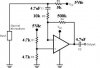
I am using a national semi **broken link removed** (though only using one of the two amps on it) as a microphone preamp. I followed the datasheet to a T, but I feel like I am missing something vital. I am using the parts that the schematic spells out (seen in the schematic attachment).
If I power the circuit with 5V and have "nothing" going through the mic, I see Vcc/2 at the V+ and V- pins like I would expect and ~0V on the output.
If I start making noise into the mic, I see the V- pin start to fluctuate (which I can believe) and I start getting a voltage out of the output. But if I scope the output, I see the voltage swinging above an below 0V (sometimes as high/low as 3.3V/-3.3V, but always centered at 0V.
At first I thought this was normal, so I started putting a DC offset on the output to make the output stay positive (mostly). But the more I read the datasheet (I am not really an analog guy), the more I realized that I should never be getting a negative voltage out (and the mic was already being biased to Vcc through the 5V resistor). As I talk into the mic, the signal looks like what I would expect, except it is centered around 0V (almost looks like a mirror above/below the 0V line).
Does anyone else with op-amp (pre-amp) experience see where I might be going wrong and/or how I can start debugging this (I have replaced the IC, checked voltages and resistances), I am too the limit of my analog experience.
Thanks!
~J