Continue to Site

Welcome to our site!

Electro Tech is an online community (with over 170,000 members) who enjoy talking about and building electronic circuits, projects and gadgets. To participate you need to register. Registration is free. Click here to register now.

  • Welcome to our site! Electro Tech is an online community (with over 170,000 members) who enjoy talking about and building electronic circuits, projects and gadgets. To participate you need to register. Registration is free. Click here to register now.

OpAmp for Electronic Wind instrument

Status
Not open for further replies.

prprog

Member
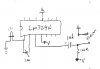
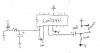
Attach is the breath controller circuit for an electronic wind instrument I am working on. My issue is that the led (which I will attach an optoisolator to control the synth volume) flicks (have fluctuations). What component should I add to smooth the response (reduce the fluctuations)? I think that capacitor should do it but have no idea where to used them and where to put in the circuit. Any suggestion will be appreciated.

Thanks
 

Attachments

  • Breath_Control.JPG
    Breath_Control.JPG
    28.8 KB · Views: 187
Hi, im not sure in what part of the project this circuit fits because i cant understand what u wrote at the input... But I have seen this type of circuit in tremolo units. First i think u biased improperly the opamp the 1u capacitor should be before the biasing resistor at the noninverting input. Second the fluctuations may occur because of the high gain the opamp has u should put a resistor in series with a 10u capacitor from the inverting input to gnd. also put a resistor (most i've seen had values from 1k2...2k2) between the output and the led.
 
(second try to post)
hentai thanks for the reply.
The input is an electrec microphone. I am a novice in electronics. I try to follow your recomendations but not sure of many points. Can you re-draw my circuit with your recomendation, I think I will understand it better.Thanks.
 
hi search the forum for electret mic preamps, i remember it has been discussed before and i dont want to upset ppl by going over it again.
the thing is at the output of the mic preamp u simply connect a 2k2 resistor in series with ur led.

P.S. if u still have problems... i'll be waiting for ur questions
 
Last edited:
An electret microphone needs to be powered by a 10k resistor to the positive supply. Your circuit has 100k which is way too high.

Pin 3 of the opamp needs to be DC-biased properly.

Then negative feedback sets the gain. The gain of your circuit is way too high.

Look at Electret Microphone and Opamp Tutorial in Google.
 
I try the following corrections to the circuit and it behave like I want. (by experimentation - at some point I read about the capacitor-resistor pair to "smooth signals" .The LED does not flicker , it light slowly (even on small signal) and turn on-off very well. (see the attach diagram)

Few notes and questions :
(I powered the circuit with a 9 volt baterry)

[1] If I change the electret to be powered by a 10k resistor the led stay on all the time (I put back the 100k resistor) . Why is this so?

[2] The capacitor needs to be a 470 uf polarized . Why?

[3] I don't understand the statement "Pin 3 of the opamp needs to be DC-biased". Can you please explain?
 

Attachments

  • Breath_Control.JPG
    Breath_Control.JPG
    12.4 KB · Views: 166
Last edited:
1). Ur circuit still has huge gain. When u use the 10k the mic outputs more signal and when combined with the huge gain the led is always on
2). What u did there is sort of a delay unit. It takes some time for the capacitor to charge and discharge thats why it doesnt flicker
3). At pin 3 u have the base of a transistor that needs some "standby" current to function properly. So u must put a resistor between pin 3 and a biasing voltage usually half the supply
 
You need to learn about opamps to know why the pin 3 input needs to be DC-biased properly.

The DC output voltage of the LM324 opamp that has a voltage gain of 1 will be the same as the DC input voltage. Your input doesn't have a DC bias voltage so its input current will cause the input voltage to be close to the positive supply voltage. Then the output will also be close to the positive supply voltage which turns on the LED.

You need to learn about opamps to see how to make them have voltage gain. Your opamp has a voltage gain of only 1. The pot does nothing without another resistor connected to it making a voltage divider.

You need to learn about electret microphones to see why a 10k resistor is needed to power it with about 0.5mA.

You also need to learn about AC signals. They cycle in a positive direction then in a negative direction. Your opamp will cause the LED to light when the AC signal from the microphone is amplified high enough and goes in a positive direction for half the time of any sound.
 
audioguru said:
Your opamp has a voltage gain of only 1.
Ur right... i was thinkig of open loop gain when i didnt saw the feedback network... i need learning myself.
 
Status
Not open for further replies.

Latest threads

New Articles From Microcontroller Tips

Back
Top