Hello everyone.
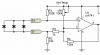
This circuit is used to detect a certain temperature level.
Honestyl I don't fully understand it. I know how it works, and how to use it, but I'd like to go deeper.
It is not a Schmitt trigger comparator (no positive feedback), nor a regular comparator ( why R3 / R2? ), nor a regular amplifier, but it seems a mixture of them.
I suppose it is based on the diodes' forward voltage decreasing with temperature (~2 mV per degree or so, I think).
As soon as the inverting input goes below non-inverting input, the output goes low, and triggers and external transistor driven circuitry.
In simulation, I tried removing the feedback, and it works, and also if attaching diode cathodes to ground (omitting the effect of R3). Of course, the response varies, but the basic function of voltage level detection/comparator is still there.
How should I face the analisys of this op amp topology?
Thanks!

")
