Continue to Site

Welcome to our site!

Electro Tech is an online community (with over 170,000 members) who enjoy talking about and building electronic circuits, projects and gadgets. To participate you need to register. Registration is free. Click here to register now.

  • Welcome to our site! Electro Tech is an online community (with over 170,000 members) who enjoy talking about and building electronic circuits, projects and gadgets. To participate you need to register. Registration is free. Click here to register now.

Op-amp, use LM324 for LM741?

Status
Not open for further replies.

upand_at_them

Active Member
I've mostly worked with digital stuff, but I recently got one of Forrest Mim's books with op-amp circuits and constructed the "Sine Wave Oscillator" using an LM324 instead of an LM741. I'm not seeing any output.

Is this an appropriate substitute? I chose the LM324 because it's single-supply.

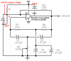
Here's the original circuit:
sineosccircuit.png

All I did was use one of the op-amps in the LM324 in place of the LM741, with Vcc to 5V and GND to ground.
 
Last edited:
For this you would only need 1/4 of the 324 (one op-amp), but the pin numbers would definitely be different. Make sure you match up the correct labels (inputs, output, Vcc and GND) with the correct pins. Pin 6 of the 741 is probably not the same as pin 6 of the 324.
Der Strom

EDIT: You may find these useful:

Pinout of the 741:
**broken link removed**
Pinout of the 324:
**broken link removed**
 
Last edited:
Sorry, maybe I wasn't clear. I am familiar with the pinout and know that I only use 1/4 of the LM324. My question is if this is an appropriate substitute since I can't measure anything at the output.
 
You need the negitive supply as well as +5 and ground so the op amp bias is correct.
 
I .... constructed the "Sine Wave Oscillator" using an LM324 instead of an LM741. I'm not seeing any output.

Is this an appropriate substitute? I chose the LM324 because it's single-supply.

All I did was use one of the op-amps in the LM324 in place of the LM741, with Vcc to 5V and GND to ground.
You cannot doo dat!

With a dual-polarity supply, the input of the opamp is biased at 0V (ground) which is "half the supply voltage". Then the input and output can swing up and down.
In a circuit using a single supply then you must use a voltage divider with two resistors and a filter capacitor to make "half the supply voltage" to bias the + input of the opamp so that the input and output can swing up and down. Any opamp will work but the LM324 quad or the LM358 dual are nice because they work when the supply is only 3.0V.

The circuit is missing parts that control the output amplitude so it will be too much and cause clipping distortion.
The LM324 and LM358 are noisy (hiss) and have crossover distortion.
 

Attachments

  • twin-T oscillator.PNG
    twin-T oscillator.PNG
    23.7 KB · Views: 1,478
Well, to put Audio McDuck's reply in perspective, he's correct about the 1/2-supply biasing necessary to use a single supply. But I'd forget about his suggested capacitors, and completely disregard his usual dire warnings about hiss, crossover distortion, etc. For chrissakes--it's a lousy twin-T oscillator! Who gives a ****? It'll work just fine without those two capacitors. The O.P. is not building a critical piece of high-fidelity equipment here. Sheesh.

By the way, my circuit here does the same thing (low-frequency twin-T oscillator) with a single transistor.
 
Cool, it works:
sineosc.png

Thanks, guys. I appreciate the explanations.

I'm going to try the transistor oscillator too.
 
Last edited:
Status
Not open for further replies.

Latest threads

New Articles From Microcontroller Tips

Back
Top