Continue to Site

Welcome to our site!

Electro Tech is an online community (with over 170,000 members) who enjoy talking about and building electronic circuits, projects and gadgets. To participate you need to register. Registration is free. Click here to register now.

  • Welcome to our site! Electro Tech is an online community (with over 170,000 members) who enjoy talking about and building electronic circuits, projects and gadgets. To participate you need to register. Registration is free. Click here to register now.

op-amp triangle wave, need help

Status
Not open for further replies.

Sparrow338

New Member
Hi all, (first post here)

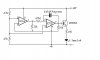
What I'm trying to do is to create a triangle wave using op-amps so that I can make a LED fade on then fade off. At the moment I'm using the circuit that I attached.

The first problem I'm having is getting the attached circuit to even work. Using the values that are shown in the schematic all that happens is the LED comes on and then stays on. I tested the op-amp outputs for any kind of wave form and there is nothing at either output.

I've tried adjusting the values of the components and the best I can get the circuit to do is to make the LED fade on, put after that it just gets stuck on and doesn't fade back off. To do this I changed out the resistor that goes from pin 7 to ground from a 4.7k Ohm to a 1k Ohm.

I understand how to an op-amp can be used to create a square wave but I don't totally understand how two can be used to create a triangle wave. So most of the component adjusting I've been doing is just randomly swapping out parts.

Oh yea I'm using the LM358.

Anyways any help would be greatly appreciated.

Thanks!

[Edit]: I probably should have said that I've done quite a bit of googling for different circuits and tried quite a few and have had similar problems with all of them.

-Sparrow
 

Attachments

  • fading-led-by-lm358.jpg
    fading-led-by-lm358.jpg
    18.3 KB · Views: 2,501
Last edited:
[Edit]: I probably should have said that I've done quite a bit of googling for different circuits and tried quite a few and have had similar problems with all of them.

-Sparrow

hi,:)
You will not get a good dimming control of an LED using this method.

Commonly used are PWM [pulse width modulation] circuits.
You could use an OPA to generate a square wave, where the on/off time drive to the LED can be varied.

The 555 timer ic makes a simple PWM osc.
 
Last edited:
You create a triangle from a square wave by sending the sq wave into an integrator, which can be made from an op-amp.

I agree a sq wave with varied ON time is a better way to change brightness.
 
Last edited:
reply

Generating Triangle Waves

In the basic square wave generator circuit, a gradually-charging capacitor was used to help set the timing or frequency of the circuit. However, since it was only charging through a resistor, it necessarily charged on a logarithmic curve, rather than as a linear ramp. Can we use an op amp integrator here to obtain a linear triangle wave along with the square wave?


--------------------------------------------------------------------------------

In the circuit to the right, we use a separate integrator to generate a ramp voltage from the generated square wave. As a result, we can get both waveforms from a single circuit. The phase relationship shown between the two output waveforms is correct — remember that the integrator inverts as well as integrating, so it will produce a negative-going ramp for a positive input voltage, and vice-versa.

Because we are now using an op amp integrator to get the triangle wave, we no longer have a logarithmic response anywhere in the circuit. Therefore, the equation for the operating frequency is simplified to:

fout = 1 ( R2 )

--------------------------------------------------------------------------------

--------------------------------------------------------------------------------

4RtC R1

The squarewave amplitude is still the limit of voltage transistion, which we are assuming here to be ±10 volts. The triangle wave's amplitude is set by the ratio of R1/R2.
 
Your circuit does not work because pin 3 of the opamp is shorted to ground instead of having positive feedback.
Also, your timing resistor is much too high at 4.7M, it should be 47k then the timing capacitor value should be much higher. The circuit I show uses two polarized capacitors back-to-back so that they pass AC.
The circuit works best with a single red LED. Two red LEDs in series will be off most of the time and fade on for a very short time.
 

Attachments

  • fading LED.PNG
    fading LED.PNG
    27.8 KB · Views: 836
Last edited:
Thank you all for the fast responses. I have a much better understanding of how this works now. I got it working using the schematic that audioguru posted.

Incase you wanted to see what it looks like here's a youtube link to a video of it. I'm planning on etching a board for it soon, but here's a quick mock-up.

YouTube - LED Fader using LM358

Thanks again for the help!
 
Status
Not open for further replies.

Latest threads

New Articles From Microcontroller Tips

Back
Top