Continue to Site

Welcome to our site!

Electro Tech is an online community (with over 170,000 members) who enjoy talking about and building electronic circuits, projects and gadgets. To participate you need to register. Registration is free. Click here to register now.

  • Welcome to our site! Electro Tech is an online community (with over 170,000 members) who enjoy talking about and building electronic circuits, projects and gadgets. To participate you need to register. Registration is free. Click here to register now.

op-amp stray-capacitance

Status
Not open for further replies.

RS_Vimperk

New Member
Hello,

i posted the problem as png file.

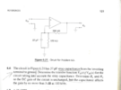
The first question is to determine the transfer function for the circuit taking into account the stray capacitance. Using voltage-devision rule, i dervied the tf and it was correct, same as the answer at the end of book.

\[ \frac{v_{0}(s)}{v_{in}(s)}= 3.5(1+3.17*10^{-6}s) \]

The second question is to determine R1 and R2 so the DC gain of the circuit is unchanged. What i understand is when DC, then capacitor is open so we get only resistances and since s=0 the transfer function has the value 3.5, and according to this rewriting the formula, we have

R2=2.5 R1

which is also good, the answers at the end of book show that R1=60.2 k, R2=150.6 k

so it's right that R2=2.5 R1

now i'm not sure about that part that says that the capacitance affects the gain by no more than 3 dB at 100 kHz. Can you guide me?

R2 is the feedback resistor.

Thanks.
 

Attachments

  • op-amp stray-capacitance.png
    op-amp stray-capacitance.png
    62 KB · Views: 181
At low freq we have classic G = 1 + R2 / R 1, R2 = 300k.....

So calc that G in db, take away 3 db, and translate back to linear G.
Or just use your rule of thumb 3 db down = .707.....

That then tells you what the z of the combo of R1 and Cstray must
be, in turn you can then find out what freq thats at to create that Z.


Regards, Dana.

I'm not sure if i understand, the goal is to determine R1 and R2 so that the gain is not affected by no more than 3 dB at 100kHz. Can you explain in more mathematics?

We actually need to calculate a new values of R2 and R1 for that frequency.
 
We actually need to calculate a new values of R2 and R1 for that frequency.
The ratio of R1 to R2 must remain fixed, as the DC gain must stay the same.

The question comes down to how low a value must the (presently) 120K resistor be, so adding 43K in parallel changes the ratio by no more that root 2, then setting a proportional value in place of the 300K to maintain the ratio.

eg. A simple and useable solution would be to divide both resistors by ten, fifteen or more, so adding the 43K in parallel has a minimal influence on the ratio - but I suspect the correct solution is to find values that just meet the question criteria.
 
I'm not sure if i understand, the goal is to determine R1 and R2 so that the gain is not affected by no more than 3 dB at 100kHz. Can you explain in more mathematics?

We actually need to calculate a new values of R2 and R1 for that frequency.
You start here -

1664284384232.png


So compute Vout / Vin = G for - 3 db.

Then move on the computing the R's for the G, in this case the Z's since its at 100 Khz and a
reactive component is in the fdbk loop.


Regards, Dana.
 
Here is a sim just for reference before you do the calculations. Note the problem
assumes an ideal OpAmp, eg. infinite GBW, but real OpAmps have limits in many
performance aspects. Notice sever peaking that occurs, you can actually do AC
analysis and predict this.

1664299221828.png


Regards, Dana.
 
I tried to calculate R2 and R1, taking into consideration that R2=2.5*R1

\( A_{v}(dB)=20*log (\frac{v_{out}}{v_{in}})= 20*log(3.5)=10.88 dB \)

i took away 3dB and it becomes 7.88 dB

then

\[ 7.88=20* log(\frac{v_{out}}{v_{in}}) \]

when i substituted Z as R1 in parallel with Xc and as Xc=43k

but actually i got a negative value of R1.

There should be something wrong with my calculations.
 
\[ 7.88=20*log(\frac{v_{out}}{v_{in}})\\ \frac{v_{out}}{v_{in}} = 10^{\frac{7.88}{20}}=2.477=1+\frac{R_2}{Z}\\ \frac{R_2}{Z}=1.477\\ \frac{R_2}{\frac{R1*X_c}{R_1+X_c}}=1.477\\ R_2=2.5*R_1 => 2.5*\frac{R_1+X_c}{X_c}=1.477\\ 2.5*R_1+2.5*X_c=1.477*X_c => 2.5*R_1=-1.023*X_c \]
 
The answers should be R1=60.2k, R2=150.6k

According to the textbook.

So there is something wrong in this mathematics, i think we lack knowledge of theory that leads us to wrong results, resistor can never be negative and moreover even the absolute value is wrong.
 
300K / 120K = gain of 3.5 with the original circuit.
150.6K / 60.2K = gain of 3.501, near enough.

60.2K in parallel with 43K = 25.08K

150.6K / 25.08K = gain of 7.
A 3db gain change from 3.5 would be to about a ratio of 4.95, not 6.


The book answer is apparently wrong; it's not all that rare.

Also:
I tried to calculate R2 and R1, taking into consideration that R2=2.5*R1

Av(dB)=20∗log(voutvin)=20∗log(3.5)=10.88dBAv(dB)=20∗log(voutvin)=20∗log(3.5)=10.88dB A_{v}(dB)=20*log (\frac{v_{out}}{v_{in}})= 20*log(3.5)=10.88 dB

i took away 3dB and it becomes 7.88 dB

Remember that effectively reducing the value of R1 in proportion to R2 with increase the gain, not decrease it!

You should have added 3db in there.
 
Can you explain in more mathematical way? I just feel lost between the words.

As for the book's answer, it can be wrong, however when i solved other problems i didn't find any single mistake (up till now). I mean there could be errors but not that essential, for example only in the fraction after the whole number.

Even if those numbers are incorrect, i would like to perform a more comprehensible approach to understand all the process, should that be possible, of course.

Thank you all so much for your cooperation.
 
The answers should be R1=60.2k, R2=150.6k

According to the textbook.

So there is something wrong in this mathematics, i think we lack knowledge of theory that leads us to wrong results, resistor can never be negative and moreover even the absolute value is wrong.

Actually in circuit analysis not uncommon to see a -R element. But this circuit no.

I dont see you doing the magnitude of the Z, which eliminates - signs as every term
is squared and then rooted to get magnitude of the Z. Post # 10


Regards, Dana.
 
Last edited:
Can you explain in more mathematical way? I just feel lost between the words.
You need to understand the circuit operation before you can do any maths, otherwise the math is irrelevant or incorrect.

eg. Shunting the 120K in the original circuit can only over lower the effective value and increase the circuit gain.
However you calculated for a decrease in gain - which means making the 120K (or whatever replaces it) higher in value, in proportion to the 300K position.

That can only be done in practice by adding a series component - or in maths by adding a negative resistance in parallel, which is why you got crazy results.

That would not have happened if you had properly thought about how the circuit works, before jumping in to (irrelevant, due to a misconception) over-complex calculations.

You need to look at whatever circuit you are working on and visualise its operation, and be able to rough out results in your head, before you start doing precision calcs - if they are ever actually needed, which they are not in a lot of real-world design work; simple mental calculations are often more than sufficient.

eg. My "Divide both by ten" solution in post #6 - it fits the requirements of the question and would be a simple real-world solution to the problem. If the resistor value is small in comparison to the capacitor impedance, the gain change is also going to be small. My ballpark mental calculation put the gain increase at somewhere around 30% or so, safely below the 41% increase limit (100% -> 141%; 1 / 0.7071, which is root 2).

Yes, a calculator is needed for such as capacitive and inductive reactance, resonant frequency and RF calculations - but very rarely for general projects.

It's real-world reality - Even if you choose to use E96 series 1% resistors, that means no resistor is guaranteed to be closer that 1% to it's nominal value and the steps between values are about 1.5%

More likely you would choose from E24 values, which have a step between values of roughly 10%.

And most capacitors are 5% or 10% tolerance, unless you pay crazy prices.

You have to design things to work with lack of precision in normal components, so there is frequently no point calculating at multi-digit accuracy, as long as you understand the principles and can do that if it's ever needed.

If a circuit needs extreme precision, then you use adjustable components in appropriate key locations - trimmer (preset) resistors and capacitors, often in conjunction with a fixed component to limit the adjustment range and increase adjustment accuracy.
Those can be used calibrate things and compensate for inaccuracies in other components, and allow for component aging and drift, so the device or instrument etc. can be recalibrated at times to maintain its precision.
 
Actually in circuit analysis not uncommon to see a -R element. But this circuit no.

I dont see you doing the magnitude of the Z, which eliminates - signs as every term
is squared and then rooted to get magnitude of the Z. Post # 10


Regards, Dana.


You are right. I re-wrote the formula.

\[ \frac{2.5*|R_1-j X_c|}{|-jX_c|}=1.477\\ 2.5*\sqrt (R_1^{2}-X_c^{2})=1.477 *|-j X_c| \\ 6.25*(R_1^2-X_c^{2})=2.18*X_c^2 \\ R_1= 50k\\ R_2=2.5*R_1=125k \]

Does that sound reasonable?
 
Last edited:
Status
Not open for further replies.

Latest threads

New Articles From Microcontroller Tips

Back
Top