Electro Tech is an online community (with over 170,000 members) who enjoy talking about and building electronic circuits, projects and gadgets. To participate you need to register. Registration is free. Click here to register now.
Welcome to our site! Electro Tech is an online community (with over 170,000 members) who enjoy talking about and building electronic circuits, projects and gadgets. To participate you need to register. Registration is free. Click here to register now.
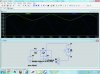
Your circuit is an integrator. It won't give the output waveforms shown (which are appropriate for a differentiator).
An integrator is often used, for example, to generate a triangle wave in pulse-width-modulation applications.
A common use for a differentiator is edge-detection of square-wave signals.
hello,
I am using sin wave and the output is -cos wave as we have formula of it sin x dx = -cos x + C
what does C mean here?
and changing value of R and C what will happen is there any formula of it?
Does the op amp is negative feed back with capacitor?
how to drawn this gain graph? **broken link removed**
Integration and differentiation are not the same thing. In post #5, your equation is for differentiation but your schematic is an integrator. This makes it very difficult to provide an answer. If you do not understand the basics of calculus, and basic opamp gain equations, then opamp circuits to implement calculus equations will not make sense.
Hello,
I am working with this equation the output is cos wave which is in negative region but what does this C mean?
whatwaht is the practical application of sin integrate to -cos? sin x dx = -cos x + C
Just so you know, ESDR has been banned as this name is an alias for someone who has been banned many times in the past. Feel free to keep discussing for future readers, but there is no need to address the OP any further.
C can be viewed as a DC level that can exist on the integrator output at the start of the integration time.
If you integrate a sine wave, you get a cosine wave.
This site uses cookies to help personalise content, tailor your experience and to keep you logged in if you register.
By continuing to use this site, you are consenting to our use of cookies.