Hi All,
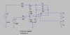
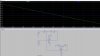
Can anyone help me set-up my equations for the closed loop gain of this circuit? It's been a while since I've done the calculations and would like to brush up on it. Thanks for the help.
Hi there,
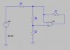
The first thing you have to think about is just how theoretical or how practical you want to get with this circuit. For example, assuming the gain of U1 is infinite and has fast response (often appropriate assumptions) we can immediately eliminate C2, C3, and R5. This would leave us with a much simpler system where we have an AC amplifier with a DC bias.
Using nodal analysis the defining equation for the output of the op amp with infinite gain comes out to be:
Vout=-(s*C2*E2*R1*R2*R4+E2*R1*R4-s*C1*E1*R1*R2*R3-E1*R2*R3+E2*R1*R2-E1*R1*R2)/((s*C1*R1+1)*R3*(s*C2*R2*R4+R4+R2))
where
E1 is the DC source, and
E2 is the AC source, and
some components were eliminated because of the infinite gain.
Solving for the DC output we get:
VoutDC=E1*R2*(R1+R3)/(R3*(R2+R4))
and solving for the AC output we get:
VoutAC=-(E2*R1)/((s*C1*R1+1)*R3)
where we see we have been able to reduce this to a first order response because without some components we just have an AC amplifier with DC bias.
The amplitude of the AC output is:
VoutACampl=(E2*R1)/(sqrt(w^2*C1^2*R1^2+1)*R3)
and that will of course ride on the DC output.
Note that if we wish to do a more complete analysis we would leave the gain at some finite value Ao and go from there. We end up with a much more complicated expression for the total output though:
Code:
Vout=-(Ao*(s*C2*E2*R1*R2*R4+E2*R1*R4-s*C1*E1*R1*R2*R3-E1*R2*R3+E2*R1*R2-E1*R1*R2)*(s*C3*R5+1))/(Ao*s^3*C1*C2*C3*R1*R2*R3*R4*R5+s^3*C1*C2*C3*R1*R2*R3*R4*R5+Ao*s^2*C2*C3*R2*R3*R4*R5+s^2*C2*C3*R2*R3*R4*R5+Ao*s^2*C1*C3*R1*R3*R4*R5+s^2*C1*C3*R1*R3*R4*R5+Ao*s*C3*R3*R4*R5+s*C3*R3*R4*R5+s^2*C2*C3*R1*R2*R4*R5+s*C3*R1*R4*R5+Ao*s^2*C1*C3*R1*R2*R3*R5+s^2*C1*C3*R1*R2*R3*R5+Ao*s*C3*R2*R3*R5+s*C3*R2*R3*R5+s*C3*R1*R2*R5+s^2*C2*C3*R1*R2*R3*R4+s^2*C1*C3*R1*R2*R3*R4+Ao*s^2*C1*C2*R1*R2*R3*R4+s^2*C1*C2*R1*R2*R3*R4+s*C3*R2*R3*R4+Ao*s*C2*R2*R3*R4+s*C2*R2*R3*R4+s*C3*R1*R3*R4+Ao*s*C1*R1*R3*R4+s*C1*R1*R3*R4+Ao*R3*R4+R3*R4+s*C3*R1*R2*R4+s*C2*R1*R2*R4+R1*R4+s*C3*R1*R2*R3+Ao*s*C1*R1*R2*R3+s*C1*R1*R2*R3+Ao*R2*R3+R2*R3+R1*R2)
This last expression although complicated would however allow us to study the effects of having C3 and R5 in the circuit.

")
")