Continue to Site

Welcome to our site!

Electro Tech is an online community (with over 170,000 members) who enjoy talking about and building electronic circuits, projects and gadgets. To participate you need to register. Registration is free. Click here to register now.

  • Welcome to our site! Electro Tech is an online community (with over 170,000 members) who enjoy talking about and building electronic circuits, projects and gadgets. To participate you need to register. Registration is free. Click here to register now.

Op-amp Fundamental Test

Status
Not open for further replies.

conanhaha

New Member
Hi all~
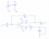
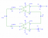
I am constructing an IC tester for op-amp now, which require to test most of the fundamental parameter of op-amp and need to make sure that, if the op-amp pass my test, then it should be working fine.

So I construct a simple circuit to test for it's parameter.
Currently I can only able to test Input offset voltage, Input offset current, Input Bias current.
So how to test the other parameter like input impedance, output impedance, CMRR, slew rate, voltage swing or any other?

This is my circuit that can test the offset current/voltage, bias current by varying the Rf, Ri, Rc value.
So what can i add in to test the other parameters and how?
 

Attachments

  • circuit.PNG
    circuit.PNG
    11.8 KB · Views: 913
  • circuit2.PNG
    circuit2.PNG
    9.8 KB · Views: 642
Last edited:
You saved your schematic as a fuzzy JPG file type so we cannot see its details.
Instead, save it and post it as a very clear GIF or PNG file type.
And please turn off those awful dots all over the place.

Why do you want to test an antique 741 opamp? Its performance is horrible. It is 42 years old and should be buried.

I designed an audio equalizer product using a TL074 quad opamp. I had tens of thousands made and tested. Not one failed the tests for supply current (12mA max), frequency response at 7 frequencies, signal to noise ratio (minimum 80dB) and distortion (0.05% max).
 
Last edited:
look for application notes...... it's usually where you find the answers to questions like this..... most manufacturers have them, and there's more useful info in them than you can imagine
 

Attachments

  • AN-24.pdf
    1.1 MB · Views: 547
Last edited:
As you hopefully have also observed, three threads started with the same problem and different names produce very few replies.
 
I designed an audio equalizer product using a TL074 quad opamp. I had tens of thousands made and tested. Not one failed the tests for supply current (12mA max), frequency response at 7 frequencies, signal to noise ratio (minimum 80dB) and distortion (0.05% max).

You must have got lots of royalty out of it then.:D
Is it true? not one failed? I mean, Ismeca, the tester machine I've been seeing always digs out defect ones.
 
I was an engineer on salary, no royalties.
One of my thousands of circuits failed the testing because the IC was installed backwards. The Texas Instruments TL074C were in the surface-mount package.
The 5% metalized film capacitors were Epcos.
 
Sorry for the picture, i reupload my test circuit again :)

Basically is using a window comparator to test the output of my test circuit.
The test circuit Rf, Ri, Rc will be varying by switch of parallel resistor to lower down its value.

I test for this IC because of my campus first year electronics 3 study about this IC and my lecturer request me to test this IC (May be he wan to use this).

For the pdf file, i had read and can't really get the point from there.
Because I can't use any hand testing but fully control by micro-controller.
So basically I just can test the IC by some maximum voltage by calculation and feed into micro-controller.

But now i got not much ideas on how to other parameters like impedance and so on can be tested through the output voltage site :)
 
Status
Not open for further replies.

Latest threads

New Articles From Microcontroller Tips

Back
Top